
SF6 Circuit Breakers/11 kV SF6 Circuit Breaker
Baocheng Electrical
11 kV SF6 Circuit Breaker — 630 A, 20 kA
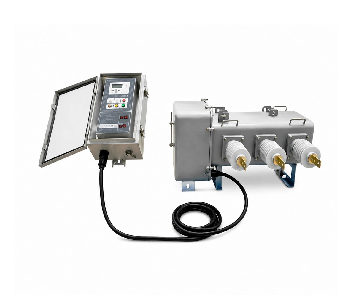
The LW6-12/T630-20 is a 12 kV-rated outdoor pole-mounted SF6 circuit breaker for 6 kV, 10 kV and 11 kV nominal systems, with a rated continuous current of 630 A and a rated short-circuit breaking current of 20 kA.
LW6-12/T630-20 · 12 kV Rated Voltage
For 6 / 10 / 11 kV Nominal Systems
630 A · 20 kA · Outdoor Pole-Mounted
Electrical profile
11 kV
Nominal system voltage
Continuous current
630 A
Short-circuit breaking current
20 kA
What Is an 11 kV SF6 Circuit Breaker?
The LW6-12/T630-20 is an outdoor pole-mounted SF6 circuit breaker for distribution switching and protection. SF6 provides the insulating and arc-interrupting medium, while a spring-operated mechanism performs opening and closing operations.
Its 630 A continuous-current rating and 20 kA short-circuit breaking rating provide the starting point for matching the breaker to the feeder load and prospective fault current.
Equipment rated voltage: 12 kV. The LW6-12/T630-20 is specified for 6 kV, 10 kV and 11 kV nominal systems. Identify the actual system voltage and frequency in your inquiry so that the protection, voltage-sensing and auxiliary equipment can be coordinated with the project.
For pole-mounted projects, include the support arrangement, conductor connections and protection interface in the inquiry. The selected assembly and its accessories should be identified in the quotation and drawings.
11 kV SF6 Circuit Breaker Specifications
Technical data for LW6-12/T630-20, based on the supplied 12 kV pole-mounted SF6 circuit breaker manual.
Electrical Ratings
| Parameter | Specification |
|---|---|
| Model | LW6-12/T630-20 |
| Nominal system voltage | 6 / 10 / 11 kV |
| Equipment rated voltage | 12 kV |
| Rated frequency | 50 / 60 Hz |
| Rated continuous current | 630 A |
| Rated short-circuit breaking current | 20 kA |
| Rated short-time withstand current / duration | 20 kA / 4 s |
| Rated peak withstand current | 50 kA |
| Rated cable-charging current | 25 A |
| Rated operating sequence | O–0.3 s–CO–180 s–CO |
Insulation and SF6 System
| Parameter | Specification |
|---|---|
| Power-frequency withstand voltage (1 min), phase-to-phase and phase-to-earth | 42 kV |
| Power-frequency withstand voltage (1 min), across open contacts | 48 kV |
| Lightning impulse withstand voltage, phase-to-phase and phase-to-earth | 75 kV |
| Lightning impulse withstand voltage, across open contacts | 85 kV |
| Insulation test pressure condition | Minimum functional pressure |
| Rated SF6 working pressure (gauge, at 20 °C) | 0.35 MPa |
| Minimum functional pressure (gauge, at 20 °C) | 0.25 MPa |
| Annual SF6 leakage rate | ≤ 0.05% |
Operating Mechanism
| Parameter | Specification |
|---|---|
| Mechanism | Spring-operated; manual and electrical energy storage, closing and opening |
| Rated operating voltage | 24 V DC |
| Mechanical endurance | 10,000 operations |
| Closing time | 40–80 ms |
| Opening time | 30–60 ms |
| Closing / opening synchronism | ≤ 2 ms |
| Contact gap | 36–38 mm |
| Contact overtravel | 20 ± 2 mm |
| Closing velocity | 2.6 ± 0.2 m/s |
| Opening velocity | 3.2 ± 0.3 m/s |
| Main circuit resistance | ≤ 120 μΩ |
Service Conditions and Housing
| Parameter | Specification |
|---|---|
| Ambient temperature | −40 °C to +40 °C |
| Altitude | ≤ 3,000 m |
| Pollution level stated in the manual | Class IV |
| Wind speed | ≤ 34 m/s |
| Breaker housing | 3 mm 304 stainless steel; sealed construction |
| Breaker housing protection | At least IP67 |
Construction and Working Principle
Sectional and Operating Mechanism Views
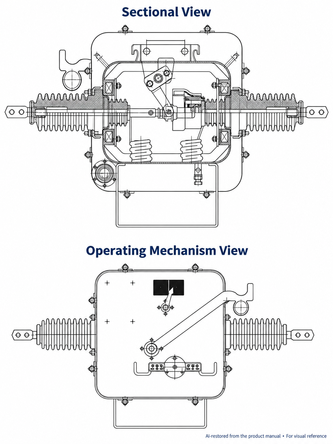
These views are AI-restored from the product manual to illustrate the breaker assembly and operating mechanism. For installation, wiring and maintenance, use the original drawings and instructions confirmed for the supplied unit.
Operating Sequence
- Fault detection: the protection system detects a fault and issues a trip command.
- Contact separation: the spring operating mechanism drives the contacts apart.
- Arc interruption: the rotating-arc system moves the arc through SF6 gas, cooling and extinguishing it so insulation is restored between the open contacts.
Coordinate the trip circuit, auxiliary power and measuring devices with the selected protection system. Confirm the control wiring and connector pin assignments against the documentation for the supplied unit.
Request the original sectional drawing, general arrangement and mounting dimensions, wiring diagrams and connector details for the supplied configuration. Use the confirmed technical documents when reviewing installation, control and maintenance requirements.
Applications and Service Conditions
Distribution Feeder Selection
Select the LW6-12/T630-20 for 6 kV, 10 kV or 11 kV nominal distribution systems. Compare the feeder load and prospective fault current with its 630 A continuous-current and 20 kA short-circuit breaking ratings.
Pole-Mounted Projects
Review the supporting structure, terminal loads, electrical clearances and access for operation and maintenance. Confirm the mounting arrangement against the selected model’s approved drawings.
Feeder Protection Integration
Where a feeder controller is required, define protection functions, measuring devices, auxiliary power and utility signals. Confirm controller and sensor supply separately in the quotation.
Service Conditions
- Ambient temperature: −40 °C to +40 °C.
- Altitude: up to 3,000 m.
- Pollution level: Class IV, as stated in the manual.
- Wind speed: up to 34 m/s.
Review the installation clearances, support structure, terminal loads and site exposure against the approved project drawings. Confirm any conditions outside the manual’s stated limits before selection.
Features and Procurement Considerations
Clear voltage identification. A 12 kV equipment rating supports selection for 6 kV, 10 kV and 11 kV nominal systems, with sensing and protection equipment coordinated to the actual network.
Technical Documents and Supply Scope
LW6-12/T630-20 Technical Documents
Request the model-specific technical package for your project:
- Technical data sheet for 12 kV rated voltage, 630 A and 20 kA.
- General arrangement and mounting dimensions.
- Terminal and control wiring diagrams.
- Installation, operation and maintenance instructions.
Inspection and Test Documentation
The manual lists a product conformity certificate, factory test report and technical manual as delivery documents. Specify additional inspection or type-test evidence in your inquiry. Any report used for technical approval must cover the offered model, ratings and configuration.
Supply Scope to Confirm
- Circuit breaker and operating mechanism.
- Mounting hardware and connection accessories.
- External controller, sensors and auxiliary power equipment, where specified.
- Interconnecting cables and required spare parts.
- Inspection, packing and project delivery requirements.
Identify each included and excluded item separately in the quotation.
The quotation should distinguish the breaker from any external controller or accessories. Define inspection requirements, spare parts and packing requirements before finalizing the order.
11 kV SF6 Circuit Breaker FAQ
Use 11 kV as the nominal system voltage in your inquiry. Confirm the equipment rated voltage (Ur) and required insulation levels against the selected breaker’s nameplate, approved data sheet and project specification before technical approval.
It is the specified rated short-circuit breaking current. It is different from the 630 A continuous-current rating and must not be substituted for short-time withstand or short-circuit making ratings.
The controller and associated sensors or cables should be identified in the agreed supply scope. Include the required protection functions, signals and auxiliary supply in your inquiry so the complete arrangement can be defined.
Include the proposed pole-mounted arrangement with your specification. The selected model, support hardware, connections and clearances must be checked together before the installation configuration is agreed.
State the available supply voltage and whether it is AC or DC. The coil, mechanism and controller requirements should be matched to the selected model’s wiring diagram rather than assumed from the system voltage.
Provide quantity, destination, an 11 kV system specification, required equipment ratings, fault level, mounting arrangement and protection requirements. Add a single-line diagram and site conditions where available.
Related SF6 Circuit Breakers
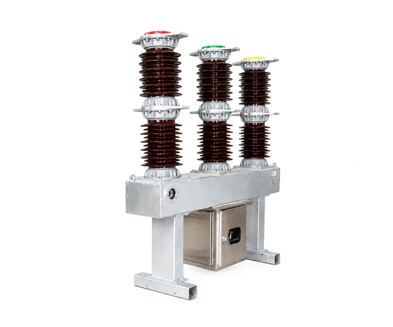
33 kV SF6 Circuit Breaker
33 kV · 1600 A · 31.5 kA
Compare this configuration for utility and industrial distribution projects. Confirm the offered model and insulation requirements in the technical quotation.
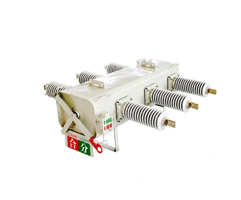
24 kV SF6 Gas Circuit Breaker
24 kV · 630 A · 25 kA
Compare this configuration for medium-voltage distribution. Confirm the insulation level, mounting arrangement and operating duty for your project.
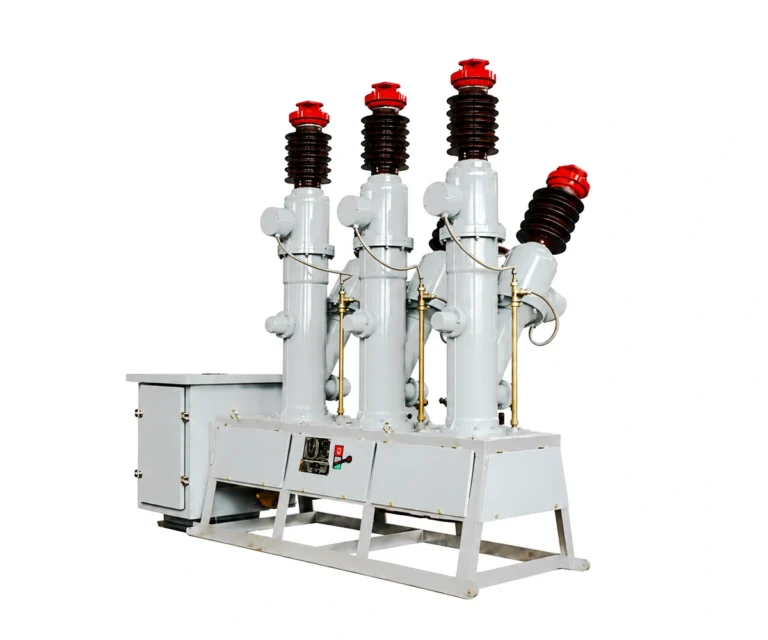
35 kV Gas Circuit Breaker
35 kV · 2000 A · 31.5 kA
Review this configuration for substation projects. Match insulation level, operating duty and installation conditions to the project specification.
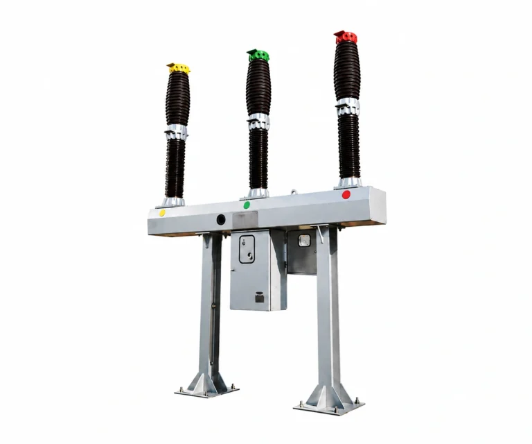
132 kV SF6 Circuit Breaker
132 kV · 2000 A · 31.5 kA
Review this configuration for high-voltage substation projects. Confirm the system voltage, insulation coordination and site conditions before selection.
Prepare Your 11 kV SF6 Circuit Breaker Inquiry
Send Baocheng Electrical your requirements for the LW6-12/T630-20, 12 kV-rated, 630 A, 20 kA configuration.
Information for Your Quotation
- Name, company and business email.
- Quantity, destination and required delivery schedule.
- Nominal system voltage: 6 kV, 10 kV or 11 kV; and network frequency.
- Continuous-current, fault-interruption and operating-duty requirements.
- Mounting arrangement, site conditions and terminals.
- 24 V DC operating supply, protection interface, sensors and controller scope.
- Required drawings, inspection documents and spare parts.
Use the form to send your project requirements. Your contact information is used to respond to this inquiry.