
SF6 Circuit Breakers / 33 kV SF6 Circuit Breaker
Baocheng Electrical
33 kV SF6 Circuit Breaker — 1600 A, 31.5 kA
The LW8-40.5(T) is an outdoor SF6 circuit breaker with a 40.5 kV equipment rated voltage, offered here for 33 kV nominal systems. This supply configuration has a rated continuous current of 1600 A and a rated short-circuit breaking current of 31.5 kA.
Equipped with a CT14 spring operating mechanism, the breaker provides switching and protection for three-phase, 50 Hz outdoor power installations. Match the insulation requirements, control supply and installation arrangement to your project before ordering.
LW8-40.5(T) — 40.5 kV Rated Voltage
For 33 kV Nominal Systems
1600 A · 31.5 kA · Outdoor

Electrical Characteristics
33 kV
Nominal system voltage
Equipment rated voltage
40.5 kV
Continuous current
1600 A
Short-circuit breaking current
31.5 kA
What Is a 33 kV SF6 Circuit Breaker?
The LW8-40.5(T) uses SF6 gas as the insulating and arc-interrupting medium. Its three separate poles are operated by a common spring mechanism, with a puffer interrupter directing compressed gas through the arc zone during opening.
On this page, 33 kV identifies the nominal system voltage; 40.5 kV identifies the equipment rated voltage. The selected 1600 A continuous-current rating and 31.5 kA short-circuit breaking rating must be checked against the installation's load current and prospective fault current.
Technical Specifications and Configuration
Main Electrical Parameters
Parameter
Value
Model
LW8-40.5(T)
Nominal system voltage
33 kV
Equipment rated voltage
40.5 kV
Rated frequency
50 Hz
Rated continuous current — selected configuration
1600 A
Rated short-circuit breaking current — selected configuration
31.5 kA
Rated short-circuit duration
4 s
Insulating and arc-interrupting medium
SF6 gas
Operating mechanism
CT14 spring operating mechanism
Mechanical Characteristics
Parameter
Value
Mechanical endurance stated in the manual
5,000 operations
Closing time at rated operating voltage
≤ 0.1 s
Opening time at rated operating voltage
≤ 0.06 s
Contact travel
95 ± 2 mm
Contact gap
60 ± 1.5 mm
Pole discrepancy during closing
≤ 3 ms
Pole discrepancy during opening
≤ 2 ms
Project-Specific Configuration
Current transformers, control-coil voltage, spring-charging motor supply and installation arrangement are selected for the project. Specify the required CT ratio, accuracy class, burden, number of cores and protection requirements where applicable.
The supplied manual references GB 1984-1989 and IEC 60056:1987. If the project specifies IEC 62271-100 or another edition, request the applicable conformity documentation and test reports for the offered configuration.
LW8-40.5(T) Construction and Working Principle
Interrupter and Operating Mechanism
The breaker has separate porcelain-supported poles containing the interrupters. A linkage connects the poles to the CT14 spring operating mechanism. The gas spaces are interconnected, and adsorbent is provided to control moisture and decomposition products.
Trip Command and Mechanism Release
An opening command releases the operating mechanism and drives the linkage to separate the contacts. Coordinate the trip circuit and auxiliary supply with the project's protection system.
Contact Separation and Gas Compression
As the contacts separate, the moving puffer assembly compresses SF6 gas. An arc forms between the separating arcing contacts.
Arc Interruption
The compressed gas passes through the nozzle into the arc zone, cooling the arc and supporting interruption at current zero. This is a puffer-type interruption process.
Spring Charging and Closing
The CT14 mechanism supports motor-driven and manual spring charging. Closing and opening commands can be provided electrically or manually as described in the equipment manual.
General Arrangement and Installation Interfaces
The manual illustrates different arrangements, including versions with and without current transformers. Use the drawing for the ordered configuration to check foundation positions, terminal interfaces and installation clearances.
Do not use dimensions from another model or arrangement for fabrication. Request the approved general arrangement and terminal drawings for the supplied unit.
General Arrangement and Terminal Connections
Outdoor SF6 Circuit Breaker — General Arrangement
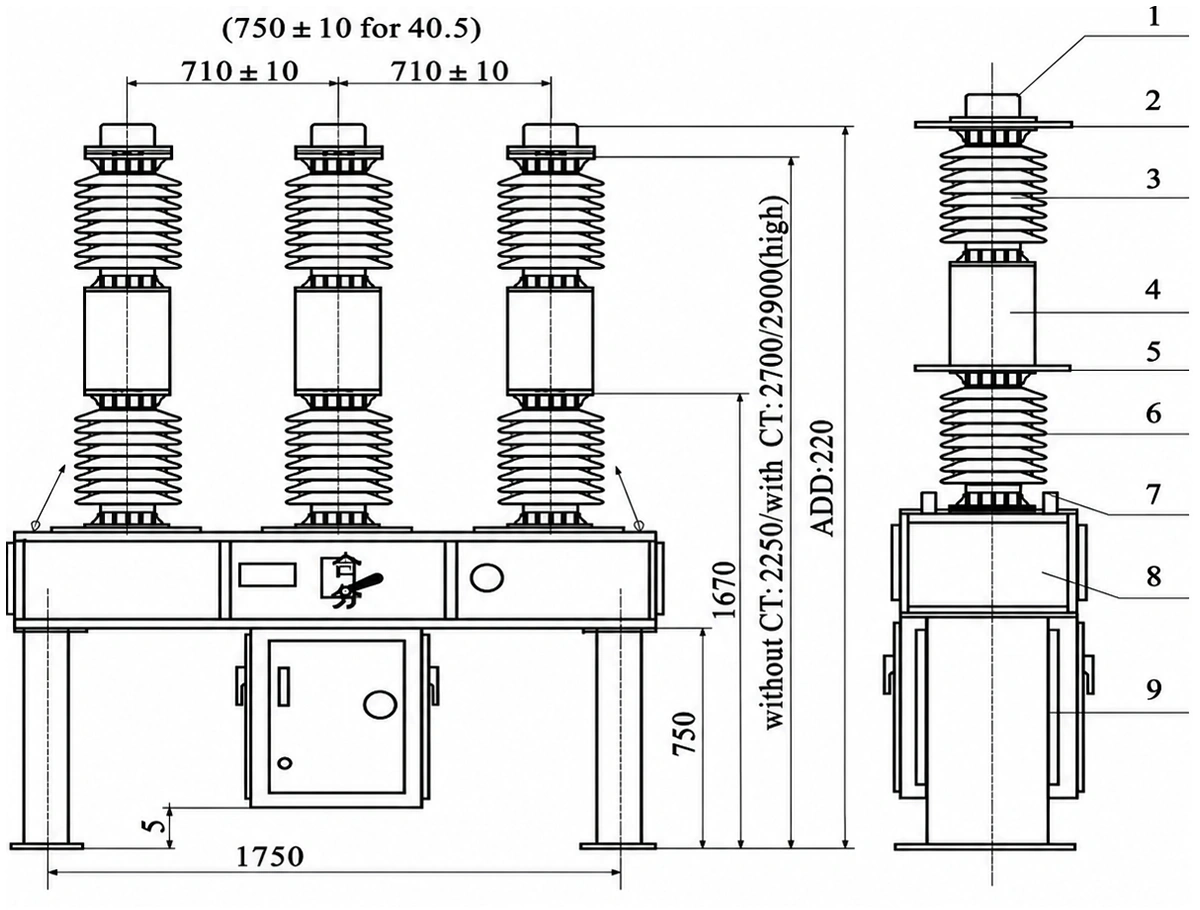
Front and side views show the outdoor breaker arrangement and numbered components 1–9. The drawing includes alternative heights with and without current transformers and a separate phase-spacing note for the 40.5 kV version. Use the approved drawing for the ordered arrangement before installation.
Aluminium Primary Terminal — Connection Dimensions
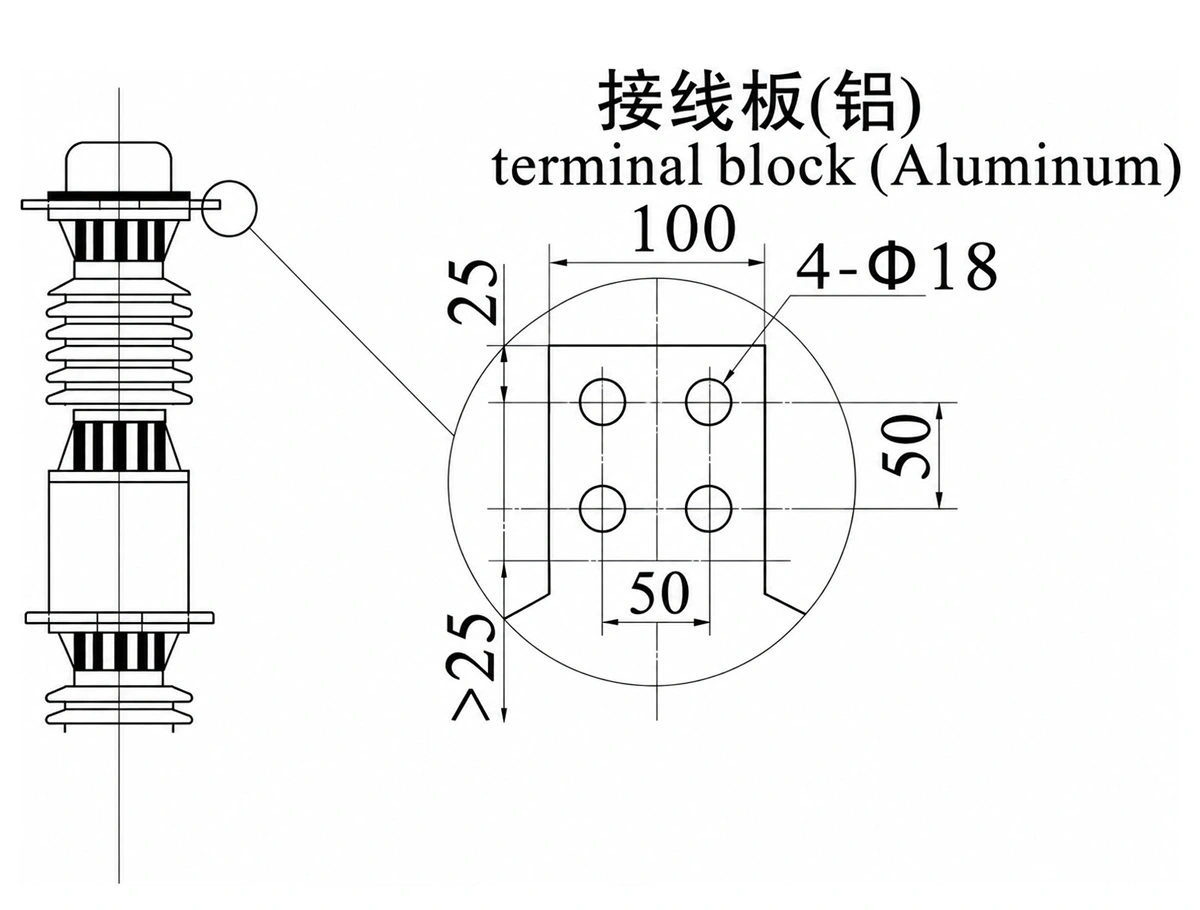
The supplied drawing shows an aluminium terminal plate with four Ø18 mm holes on 50 × 50 mm centres and a plate width of 100 mm. Check the final terminal drawing against the selected conductor or cable lug before connection.
Applications and Service Conditions
The manual describes use in outdoor transmission and distribution installations, including control and protection duties and circuit connections between sections of a network. For utility and industrial projects, specify the switching duty, protection interface and installation layout in the inquiry.
Provide the site altitude, ambient temperature range, pollution conditions and wind exposure. The manual includes different environmental and structural variants; the quotation should identify the version selected for the actual site.
Utility Switching and Protection
Specify the switching duty and protection interface for outdoor transmission and distribution installations.
Industrial Power Installations
Check the selected current and short-circuit breaking ratings against the load and prospective fault current.
Network Section Connections
Coordinate the circuit connections, operating duty and installation layout with the project specification.
Site and Service Conditions
Provide the altitude, temperature range, pollution conditions and wind exposure so the appropriate variant can be selected.
Features and Procurement Considerations
Clearly Defined Voltage Ratings
The 33 kV system designation and 40.5 kV equipment rating are stated separately to support accurate equipment schedules and technical comparisons.
Defined Supply Configuration
The selected 1600 A and 31.5 kA ratings provide a clear basis for checking load duty and prospective short-circuit current.
Puffer-Type SF6 Interruption
The interrupter uses mechanically compressed SF6 gas to cool the arc during opening.
Spring Operating Mechanism
The CT14 mechanism provides stored-energy operation. Specify the control and motor supplies to match the station auxiliary system.
Configurable Measurement and Protection Interfaces
Current transformer requirements and wiring interfaces can be identified during technical selection, with the final scope stated in the quotation.
Technical Documents and Supply Scope
The manual lists the circuit breaker, CT14 operating mechanism, product conformity certificate and operating manual as supplied items. The final quotation and contract should identify the exact equipment configuration and accessories.
For technical review, request:
- A configuration-specific technical data sheet.
- General arrangement, foundation and primary terminal drawings.
- Control wiring and auxiliary supply details.
- Current transformer data, where CTs are included.
- Applicable inspection and test documentation for the offered unit.
Spare parts, additional accessories and special requirements should be listed separately in the order. A product conformity certificate should not be described as third-party certification unless the relevant evidence is available.
33 kV SF6 Circuit Breaker FAQ
Why does a 33 kV breaker page specify a 40.5 kV rated voltage?
The two values describe different things: 33 kV is the nominal system voltage for this application, while 40.5 kV is the equipment rated voltage of the LW8-40.5(T). Verify the complete insulation requirements against the project specification.
Which current and breaking ratings are offered on this page?
This page presents the 1600 A continuous-current and 31.5 kA short-circuit breaking configuration. Other values listed in the model-family manual do not automatically apply to this selected configuration.
What operating mechanism does the breaker use?
The manual specifies a CT14 spring operating mechanism with motor-driven and manual energy storage. Select the control-coil and charging-motor supplies to suit the station auxiliary system.
Are current transformers included?
The manual describes arrangements with and without current transformers. State the required ratios, accuracy classes, burdens and protection functions, and confirm the included CT configuration in the quotation.
Does the manual establish compliance with IEC 62271-100?
The supplied manual references IEC 60056:1987 and GB 1984-1989. For a project requiring IEC 62271-100, request documentation covering the required edition and the offered configuration rather than relying on the manual reference alone.
What information is needed for a quotation?
Provide the nominal system voltage, frequency, required continuous current and breaking duty, site conditions, control supplies, CT requirements and installation arrangement. Include the project specification and any required testing or documentation.
Related SF6 Circuit Breakers
Compare the selected configuration with other products in the SF6 circuit breaker range. Check each product's equipment rating, interrupting duty and installation arrangement before selection.

11 kV SF6 Circuit Breaker
11 kV
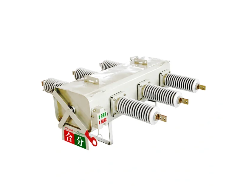
Review the 12 kV-rated LW6-12/T630-20 for 6, 10 and 11 kV nominal systems, with 630 A continuous current and 20 kA short-circuit breaking current.
24 kV SF6 Gas Circuit Breaker
24 kV
Compare this configuration for medium-voltage distribution. Confirm the equipment ratings, installation arrangement and operating duty for your project.

35 kV Gas Circuit Breaker
35 kV
Review this configuration for substation projects. Match insulation level, operating duty and installation conditions to the project specification.
72.5 kV SF6 Circuit Breaker
72.5 kV
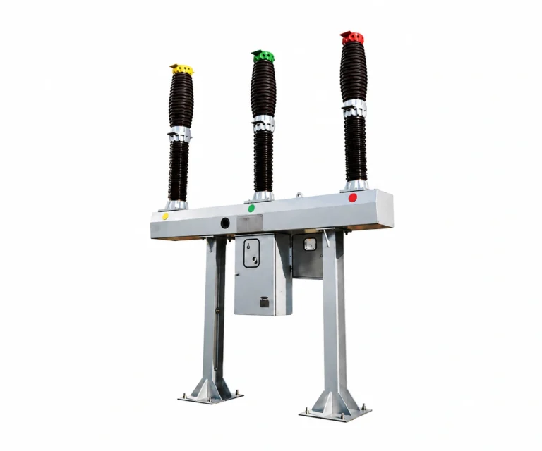
Review this 72.5 kV configuration for substation switching. Confirm system voltage, insulation requirements and installation conditions for your project.

132 kV SF6 Circuit Breaker
132 kV
Review this configuration for high-voltage substation projects. Confirm the system voltage, insulation coordination and site conditions before selection.
Request a Quotation for Your 33 kV Project
Send your requirements for the LW8-40.5(T), including the 33 kV nominal system, 40.5 kV equipment rating, 1600 A continuous current and 31.5 kA short-circuit breaking duty. Add the site conditions, auxiliary supplies, CT requirements and installation drawings so the offered configuration can be checked against your project.