Home / SF6 Circuit Breakers / 126kV SF6 Breaker
Baocheng Electrical
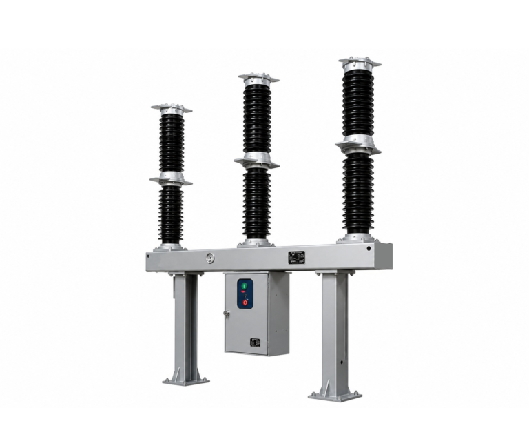
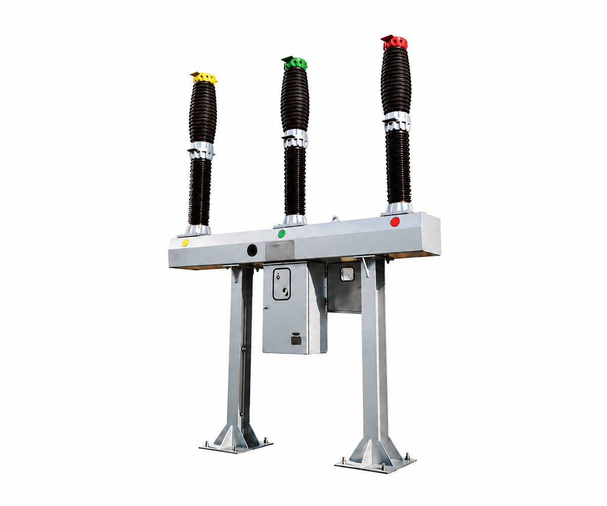
126 kV SF6 Circuit Breaker — LW36-126
Outdoor three-phase switching and protection for 110 kV nominal-system projects, with a 126 kV equipment rating and a CTB-1 spring operating mechanism.
LW36-126 — 126 kV Rated Voltage
For 110 kV nominal-system projects
3150 A · 40 kA · Outdoor
Electrical Characteristics
Nominal system voltage
110 kV
Equipment rated voltage
126 kV
Continuous current
3150 A
Short-circuit breaking current
40 kA
Product Overview
The LW36-126 is an outdoor SF6 circuit breaker with three poles and one interrupter per phase. It combines SF6 insulation and arc interruption with a common spring-operated drive for three-phase switching.
The supplied manual lists a rated voltage of 126 kV, a rated continuous current of 3150 A and a rated short-circuit breaking current of 40 kA. These equipment ratings are kept separate from the nominal voltage used to describe the power system.
Use the 110 kV nominal system as the principal selection basis for this page. Final suitability depends on the project’s maximum operating voltage, insulation coordination, frequency, short-circuit duty and service conditions.
Model Meaning
| L | W | 36 | – | 126 | (W) | / | T | 3150 | – | 40 |
|---|---|---|---|---|---|---|---|---|---|---|
| ↓SF6 circuit breaker | ↓Outdoor type | ↓Design sequence number | ↓Rated voltage (kV) | ↓Anti-fouling type | ↓Spring mechanism | ↓Rated current (A) | ↓Rated short circuit breaking current (kA) |
Technical Specifications
Main mechanical parameters of circuit breaker
| No. | Item | Unit | Value | |
|---|---|---|---|---|
| 01 | Rated voltage | kV | 126 | |
| 02 | Rated power frequency withstand voltage | To ground | kV | K·230 |
| Between breaks | K·265 | |||
| 03 | Rated lightning impulse withstand voltage | To ground | K·550 | |
| Between breaks | K·630 | |||
| 04 | Power frequency withstand voltage (5min) at retail gauge pressure of SF6 gas | K·95 | ||
| 05 | Rated frequency | Hz | 50 | |
| 06 | Rated current | A | 3150 | |
| 07 | First opening coefficient | 1.5 | ||
| 08 | Rated short-circuit breaking current | kA | 40 | |
| 09 | Rated short-circuit closing current (peak value) | kA | 100 | |
| 10 | Rated short-circuit withstand current | 40 | ||
| 11 | Rated peak withstand current | 100 | ||
| 12 | Rated short-circuit duration | s | 4 | |
| 13 | Rated out-of-step breaking current | kA | 10 | |
| 14 | Near-zone fault breaking current | kA | 90%IK, 75%IK | |
| 15 | Rated line charging breaking current | A | 31.5 | |
| 16 | Rated operation sequence | O-0.3s-CO-180s-CO | ||
| 17 | Main circuit resistance | μΩ | ≤ 40 | |
| 18 | Rated sulfur hexafluoride gas pressure (20°C gauge pressure) | MPa | 0.6 | |
| 19 | Alarm/minimum functional pressure (20°C gauge pressure) | MPa | 0.55±0.03/0.50±0.03 | |
| 20 | SF6 gas annual leakage rate | <0.5% | ||
| 21 | Gas moisture content (V/V) | ≤ 150×10-6 | ||
| 22 | Mechanical life | operations | 10000 | |
| 23 | Radio interference level | μV | ≤ 500 | |
| 24 | Creepage distance | Between fractures | mm | 3906/3150 |
| To the ground | 3906/3150 | |||
| 25 | The quality of SF6 gas filled in each unit | kg | 10 | |
| 26 | The quality of each circuit breaker | kg | 1500 | |
Note: External insulation is corrected according to the altitude correction factor K: K=1.13 for every 2000m above sea level; K=1.28 for every 3000m above sea level
Main Technical Parameters
LW36–126
Outdoor high voltage AC sulfur hexafluoride circuit breaker
Main technical parameters of the mechanism
| No. | Item | Unit | Value | |
|---|---|---|---|---|
| 01 | Auxiliary circuit voltage | V | DC220 or DC110 | |
| 02 | Opening and closing coil voltage/current | V/A | DC110/4; DC220/2 | |
| 03 | Energy storage motor | Rated voltage | V | DC220、AC220/DC110、AC110 |
| Normal operating voltage range | V | 85% ~ 110% | ||
| Power | W | 600 | ||
| 04 | Motor energy storage time | s | ≤ 15 | |
| 05 | Heater and lighting circuit voltage | V | AC220 | |
| 06 | Auxiliary switch rated voltage | V | DC220、AC220 | |
| 07 | Auxiliary switch rated current | A | 10 | |
| 08 | Auxiliary switch contacts | 10 normally open + 10 normally closed | ||
Mechanical Adjustment Parameters
The mechanical adjustment of the product is shown in the table below.
| No. | Item | Unit | Value |
|---|---|---|---|
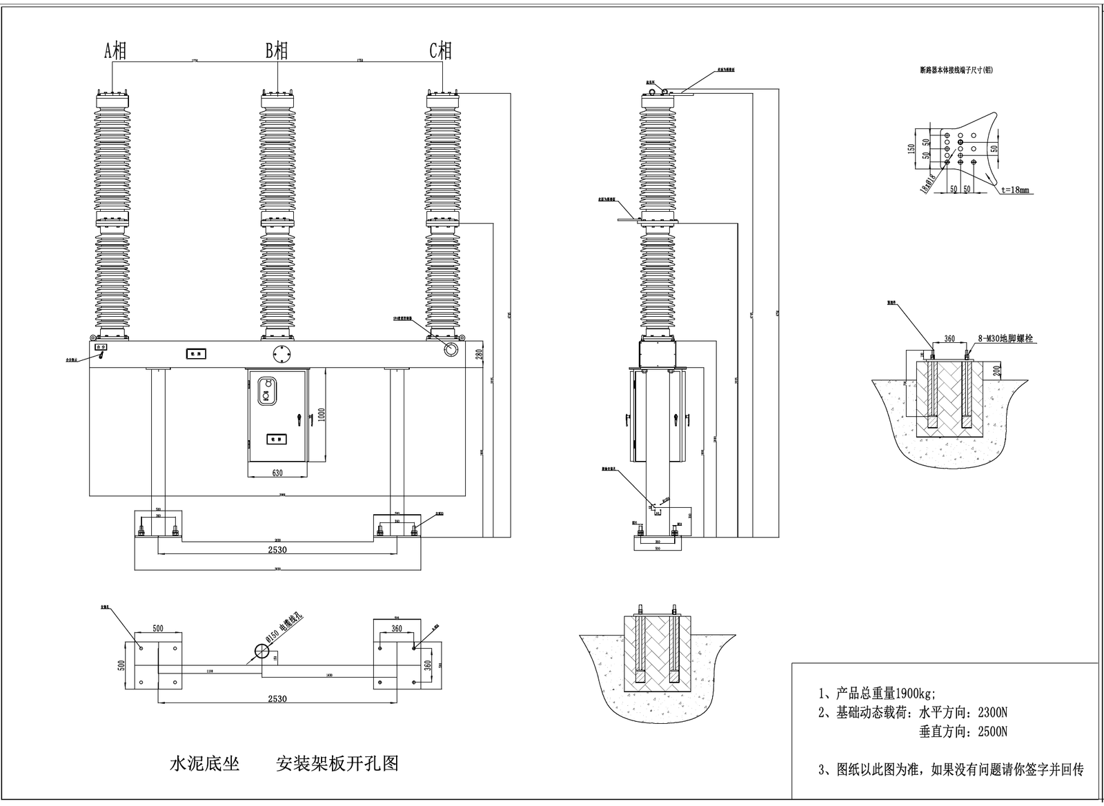
| 01 | Center distance between circuit breaker poles | mm | 1750 |
| 02 | Moving contact stroke | mm | 120+30 |
| 03 | Moving contact contact stroke | mm | 25+20 |
| 04 | Cycle length of circuit breaker interphase operating link | mm | 110+30 |
| 05 | Opening speed | m/s | 4.2-5m/s |
| 06 | Closing speed | m/s | 2.2-3 m/s |
| 07 | Opening time | ms | ≤ 40 |
| 08 | Closing time | ms | ≤ 100 |
| 09 | Opening time | ms | ≤ 60 |
| 10 | Closing-opening time | ms | ≤ 80 |
| 11 | Opening-closing time | ms | 300 |
| 12 | Three-phase opening phase difference | ms | ≤ 2 |
| 13 | Three-phase closing phase difference | ms | ≤ 3 |
Construction and Working Principle
Three-phase arrangement
Three single-break poles are supported on a common frame and operated through a common spring mechanism.
SF6 arc interruption
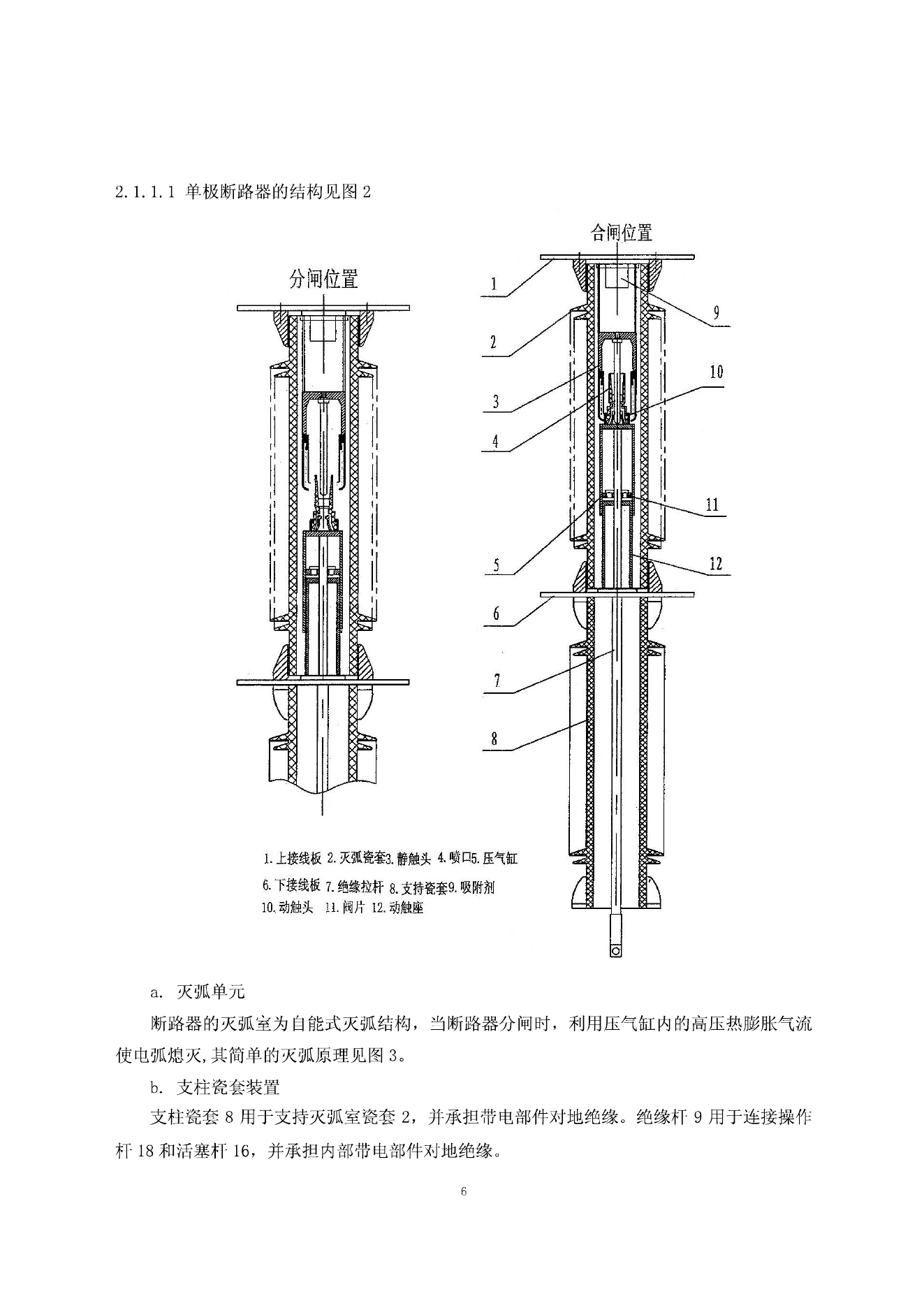
The manual describes thermal expansion with assisted gas blowing to interrupt the arc during opening.
Spring operating mechanism
The CTB-1 mechanism stores mechanical energy for closing and opening operations. Match the auxiliary supply and control arrangement to the project.
Gas supervision
The manual provides separate SF6 refill-alarm and lockout settings for supervision of the gas condition.
LW36-126 SF6 Circuit Breaker: General Arrangement & Interrupter Construction
General Arrangement
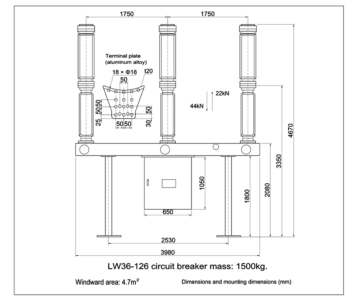
Check the approved overall dimensions, phase spacing and foundation interfaces before installation.
Interrupter Construction
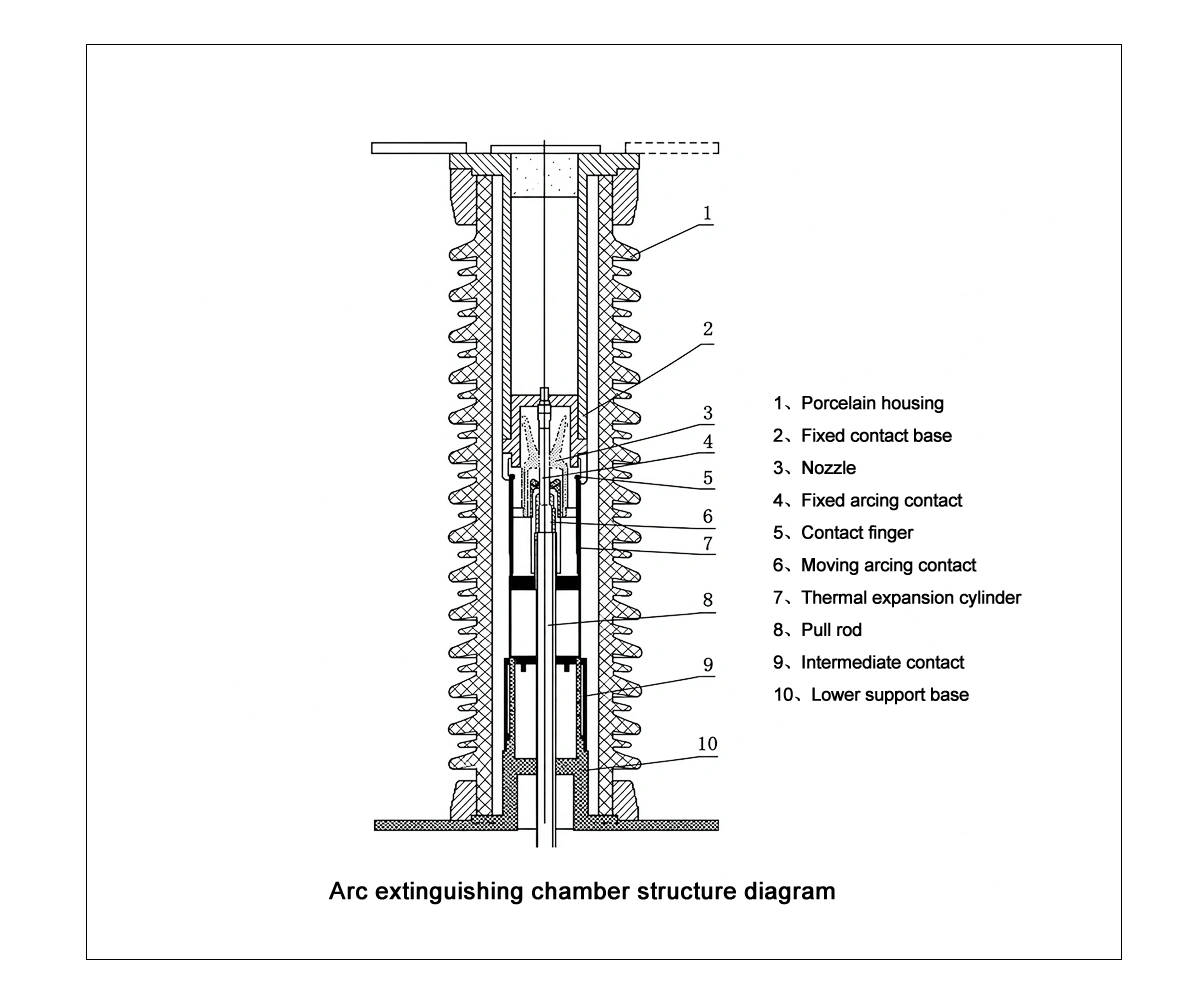
1. Porcelain housing
2. Fixed contact base
3. Nozzle
4. Fixed arcing contact
5. Contact finger
6. Moving arcing contact
7. Thermal expansion cylinder
8. Pull rod
9. Intermediate contact
10. Lower support base
Applications and Service Conditions
Consider the LW36-126 for outdoor substation switching and protection duties on 110 kV nominal systems. Line bays, transformer bays and bus-coupling duties require project-specific checks of fault level, switching duty and insulation coordination.
For industrial receiving substations or renewable-generation grid connections, assess the same electrical and site requirements before selecting the breaker. The system’s nominal voltage alone does not determine suitability.
Parameter
Value
Ambient air temperature
−30°C to +40°C
Special low-temperature condition in the manual
−40°C to +40°C — confirm the supplied configuration
Altitude limit listed in the manual
≤4500 m — confirm insulation coordination for the installation altitude
Relative humidity, daily / monthly average
≤95% / ≤90% (at 25°C)
Wind pressure
≤700 Pa
Ice thickness
10 mm
Seismic acceleration, horizontal / vertical
≤0.3g / ≤0.15g
Maximum daily temperature variation
25°C
Nominal creepage distance
31 mm/kV
The altitude and special temperature limits are manual entries, not a statement that every supplied configuration meets every extreme condition simultaneously. Confirm site pollution, creepage, altitude corrections and the required low-temperature arrangement.
Features and Practical Benefits
3150 A continuous-current rating
A clearly defined current rating for load and busbar coordination.
40 kA short-circuit breaking rating
A stated fault-interruption rating to compare with the project fault study.
Separate insulation ratings
Power-frequency and lightning-impulse levels are listed separately for phase-to-earth and open-contact duties.
Spring-operated drive
The CTB-1 mechanism and specified auxiliary supplies provide a basis for control-system coordination.
Defined gas supervision settings
Refill-alarm and lockout values can be reviewed alongside the site’s alarm and interlocking requirements.
Technical Documents and Supply Scope
The supplied manual includes technical parameters, arrangement drawings, operating-mechanism information and electrical diagrams. Use project-approved documents for installation and commissioning.
Documents to Agree for the Order
- Guaranteed technical particulars for the selected voltage, current, frequency and switching duties.
- Approved general arrangement, foundation and terminal connection drawings.
- Control schematic, terminal schedule and auxiliary-supply requirements.
- Applicable inspection and test documents, instruction manual and packing list.
Supply Scope to Confirm
Agree the breaker assembly, operating mechanism, supporting structure, terminal connectors, accessories, spare parts and document package in the quotation. Inclusion of individual items is subject to the order.
The manuals reference GB 1984-2003 and IEC 62271-100:2001. These references identify the editions cited by the manuals; they do not establish certification to a current edition. Confirm the required standard and supporting test evidence for the project.
Technical and Purchasing FAQ
Is 126 kV the nominal system voltage?
No. 126 kV is the equipment rated voltage in the manual. This page uses 110 kV as the primary nominal-system selection basis, subject to project coordination.
Can the breaker be considered for a 115 kV system?
Only after a project-specific review. Confirm the maximum system voltage, required insulation levels, frequency, fault duty and applicable standards. The 115 kV entry is not a confirmed alternative rating.
What current and breaking ratings are listed?
The model-specific manual lists 3150 A rated continuous current and 40 kA rated short-circuit breaking current. These values should be reproduced in the final guaranteed technical particulars.
Which operating mechanism is used?
The manual specifies the CTB-1 spring operating mechanism. Confirm the control supply, charging-motor supply and secondary wiring for the order.
Can the manual drawings be used directly for installation?
Use approved drawings for the ordered configuration. The reproduced drawings are manual references; foundation interfaces, terminal details and final dimensions require project confirmation.
What information is needed for a quotation?
Provide the nominal and maximum system voltage, frequency, continuous current, fault level, insulation requirements, site altitude and temperature, auxiliary supplies, required quantity and applicable standard.
Discuss Your 110 kV System Requirements
Send your project specification for the LW36-126. Include the nominal and maximum system voltage, frequency, fault duty, insulation requirements and site conditions so that the offered configuration can be checked.
Related Products
Explore related SF6 circuit breakers and compare product specifications for your project.