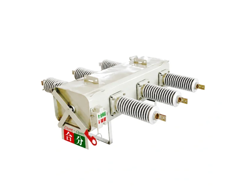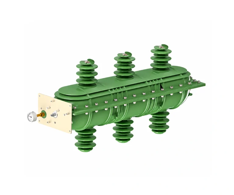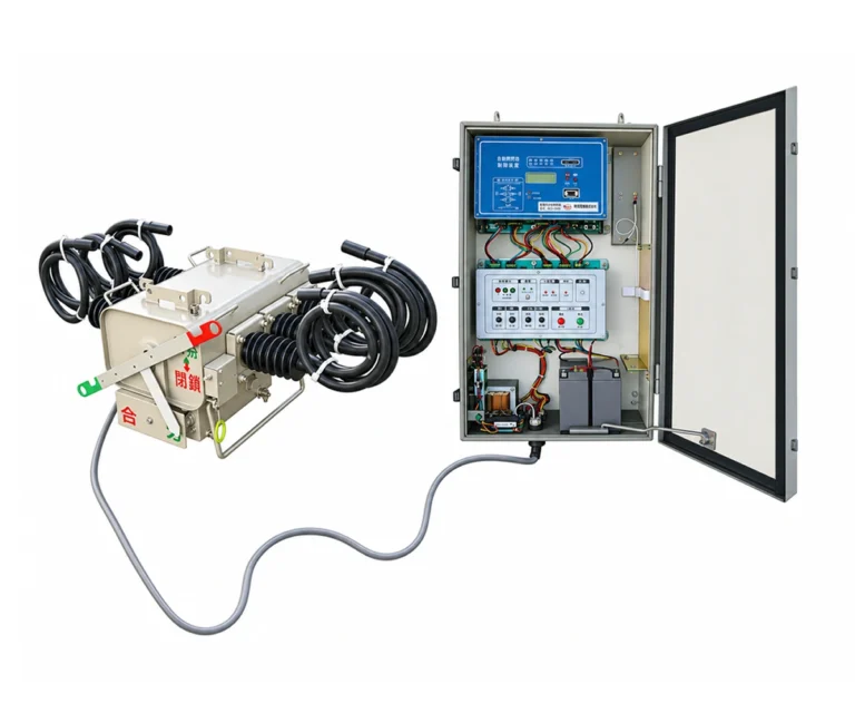
12kV Indoor AC High-Voltage SF6 Load Break Switch (FLN36 / FLRN36 Series)
The DC FLN36-12D Indoor SF6 Load Break Switch and DC FLRN36-12D Fuse Combination Apparatus are state-of-the-art medium-voltage switchgear components rated at 12kV.
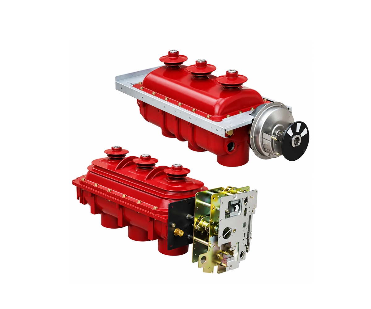
Utilizing sulfur hexafluoride (SF6) gas for superior arc-extinguishing and insulation, this 3-position switch (Closed, Open/Isolated, Earthed) is specifically designed for secondary ring main units (RMU), compact substations, and industrial power distribution systems. Backed by robust APG epoxy resin enclosure technology, it ensures exceptional environmental adaptability against high humidity, condensation, and pollution.
12 kV
11 kV
630 A
20 kA / 4 s
Product Overview
The FLN36-12 is a 12kV (11kV nominal system) indoor AC high-voltage SF6 load break switch rated at 630A, housed in a hermetically sealed, high-strength epoxy resin enclosure. Designed and type-tested in strict accordance with IEC 62271-103 and IEC 60265, it integrates load breaking, visible disconnection, and fault-making earthing into a compact three-position switching unit.
Ideal for air-insulated switchgear cubicles (such as XGN15), Ring Main Units (RMU), and prefabricated compact substations, the series is available in two primary configurations: the standard FLN36-12D (with a K-type single-spring mechanism for incoming/outgoing cable feeders) and the FLRN36-12D switch-fuse combination unit (with an A-type double-spring tripping mechanism compliant with IEC 62271-105 for reliable distribution transformer protection).
- Three-Position Safety Architecture: Combines Closed, Open (Isolated), and Earthed positions in a single interlocked rotary/linear contact system, preventing simultaneous closing of the main and earthing switches.
- Maintenance-Free Sealed Gas Tank: Cast in durable epoxy resin (APG process) with low SF6 gauge pressure (≤ 0.04 MPa at 20°C) and an annual leakage rate below 0.1%, ensuring a 30-year service life without gas refilling.
- Flexible Operating Mechanisms: Supports manual spring operation (K-type or A-type) as well as optional motorized drives (AC/DC 110V, 220V, DC 48V) and shunt trip coils for SCADA remote automation.
- Full Transformer Protection (FLRN36-12D): Easily paired with DIN-standard high-voltage current-limiting fuses; a fuse striker pin automatically triggers three-phase mechanical tripping upon any single-phase fuse blow.
12 kV Indoor SF₆ Load Break Switch Technical Parameters
12 kV Indoor SF₆ Load Switchgear Transformer Protection & Fuse Matching Table
XRNT-12
12
FLN36-12D: Design & Operating Principle
K-Type Spring Operating Mechanism
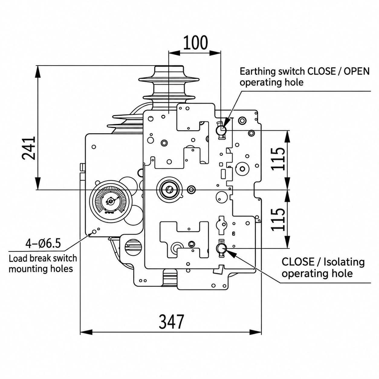
Operating and Interlocking
01 Grounding switch
When the grounding switch is closed, the load switch cannot be closed.
02 Isolation Operation
When the load switch moves from the closed position to the isolation position, for the K operating mechanism, insert the operating handle into the load switch operating hole and rotate the handle counterclockwise 180” to perform the isolation operation.
03 Installation and Commissioning
SF6 load switches undergo rigorous factory inspection before leaving the factory and meet the product’s technical requirements. During installation and commissioning, check for any external damage; any damaged products should be immediately removed from use.
Position Interlocking
The load switch is also equipped with a locking plate that connects to the cabinet to prevent accidental entry into a live compartment when the grounding switch is in the isolated position;
12kV Indoor SF6 Load Switchgear Assembly Outline Dimensions
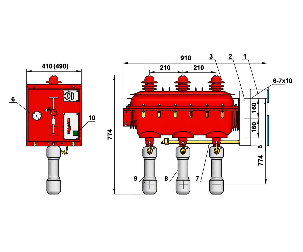
Switch-fuse assembly components
- Operating mechanism cover
- Operating mechanism
- Upper terminal shield
- Load switch body
- Lower terminal shield or upper fuse contact seat
- SF₆ pressure gauge
- Impact trip mechanism
- Fuse
- Lower fuse contact seat
- Trip pushbutton
12kV Indoor SF6 Load Switch Outline Dimensions
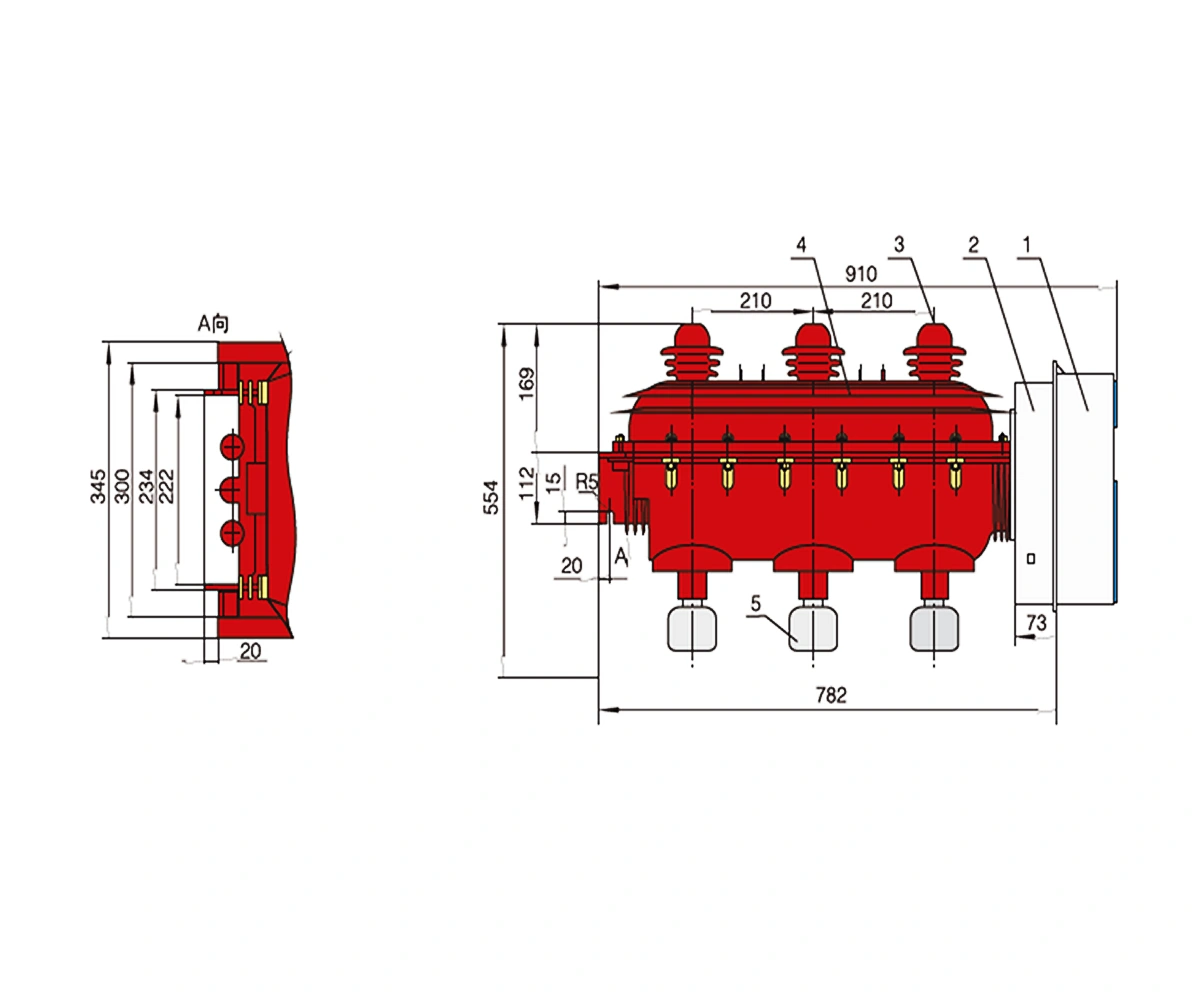
Load switch components
- Operating mechanism cover
- Operating mechanism
- Upper terminal shield
- Load switch body
- Lower terminal shield or upper fuse contact seat
Applications & System Configurations
Incomer & Feeder Unit
Utilized for power distribution, cable sectioning, and network control in medium-voltage power systems.
Transformer Feeder & Protection Unit
Configured with a fuse combination apparatus to precisely match transformer ratings, providing rapid fault clearance and transformer protection.
Key Features & Procurement Guidelines
Triple-Position Safety Interlock
High Mechanical Endurance
Wide Environmental Adaptability
Procurement Guidelines
Technical Documents and Supply Scope
Technical Documents
The manual lists a product certificate of conformity, installation and operating instructions, and a packing list among the accompanying documents. Request the approved mechanism outline and control wiring diagram for the ordered configuration.
Inspection and Test Documentation
Confirm which inspection records apply to the selected switch or switch-fuse assembly.
Supply Scope to Confirm
Specify the operating mechanism, auxiliary contacts, control supply and any required fuses.
FLN36-12 Load Break Switch FAQ
The manual identifies a 10 kV system application and a 12 kV equipment rating.
The standalone switch is rated to interrupt 630 A of active load current, 630 A of closed-loop current and 10 A of cable-charging current.
The closed switch can withstand 20 kA for three seconds. This figure describes short-time withstand duty.
The 50 kA short-circuit breaking rating applies to the FLRN36-12D/T125-50 switch-fuse combination.
Request the K-type mechanism outline for the standalone switch or the A-type outline for the switch-fuse combination. Use the approved dimensions for the cabinet layout.
Include the model, cabinet layout, mechanism, control supply, site conditions and quantity. For a switch-fuse combination, also identify the transformer to be protected.
Related Products
Explore related SF6 switching and protection equipment for your distribution project.