Medium Voltage Equipment / 40.5 kV Switchgear
Baocheng Electrical
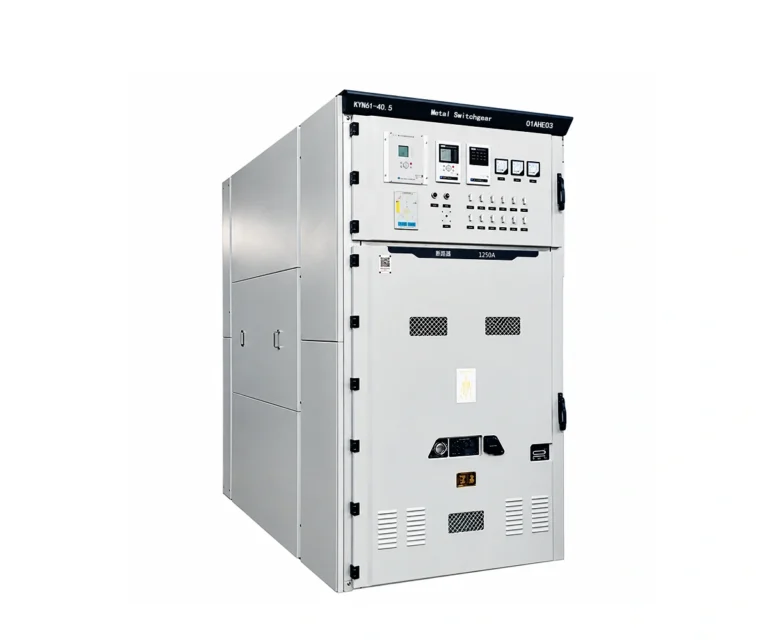
40.5 kV Switchgear
KYN61-40.5
Indoor withdrawable metal-enclosed switchgear for power distribution, control, protection and monitoring. A vacuum circuit-breaker truck and separate primary compartments support the selected feeder scheme.
40.5 kV rated voltage · three-phase · 50 Hz
1,250 / 1,600 / 2,000 A
Indoor · withdrawable vacuum circuit breaker
Electrical Characteristics
Nominal system voltage
33 / 35 kV
Rated voltage
40.5 kV
Rated current options
1,250–2,000 A
Short-circuit breaking options
20 / 25 / 31.5 kA
What Is The KYN61-40.5?
KYN61-40.5 is an indoor, three-phase 50 Hz withdrawable metal-enclosed switchgear design. The supplied document describes receiving and distributing electrical energy in generating stations, substations and industrial facilities.
A bolted cabinet structure is divided by metal partitions into circuit-breaker, main busbar, cable and relay / instrument compartments. The circuit-breaker truck has service and test / disconnected positions.
The document lists several current and fault-duty options. The selected circuit breaker, busbars, current transformers, cables and interlocking scheme must be specified as a coordinated assembly.
Technical Specification Tables
Table 1 — Main switchgear ratings
| Parameter | Catalogue value |
|---|---|
| Rated voltage / frequency | 40.5 kV / 50 Hz |
| Rated current options | 1,250 / 1,600 / 2,000 A |
| Short-time withstand current options | 20 / 25 / 31.5 kA |
| Rated duration of short circuit | 4 s |
| Peak withstand current options | 50 / 63 / 80 kA peak |
| Power-frequency withstand, 1 min | 95 kV |
| Lightning impulse withstand | 185 kV peak |
| Enclosure / breaker door open protection | IP3X / IP2X |
Source: DOCX “Main technical parameters of vacuum switchgear” and structural description. Values are listed options, not confirmation that every combination is available.
Table 2 — Vacuum circuit-breaker characteristics
| Parameter | Catalogue value |
|---|---|
| Rated short-circuit breaking current options | 20 / 25 / 31.5 kA |
| Opening time | 30–60 ms |
| Closing time | 50–100 ms |
| Mechanical endurance | 10,000 operations |
| Rated short-circuit breaking operations | 20 |
Source: DOCX vacuum circuit-breaker table. Its short-circuit duration row has an inconsistent unit; the 4 s value above is taken from the separate switchgear table.
Table 3 — Service conditions & layout
| Parameter | Catalogue value |
|---|---|
| Ambient temperature | −15 to +40 °C; 24 h mean ≤35 °C |
| Altitude | ≤1,000 m |
| Relative humidity — daily / monthly mean | ≤95% / ≤90% |
| Overall size — width × depth × height | 1,400 × 2,800 × 2,600 mm |
| Approximate cabinet mass | 1,800 kg |
| Room height | ≥4,500 mm |
| Rear clearance | ≥1,500 mm |
| Operating aisle — single row / face-to-face | ≥3,000 / ≥4,000 mm |
Catalogue arrangement values must be checked against the approved project layout. The monthly water-vapour pressure value is malformed in the source and has not been specified.
KYN61-40.5: Design & Operating Principle
Functional Overview

This diagram supports the operating description. It is not an approved primary schematic or switching procedure.
01 · Primary circuit
Insulated busbars feed branch connections and fixed contacts. The withdrawable vacuum circuit breaker connects the selected incoming or outgoing circuit.
02 · Truck & shutters
The screw-driven truck moves between test / disconnected and service positions. Shutters cover the fixed-contact interfaces as described in the source.
03 · Interlocking & protection
Mechanical interlocks coordinate the breaker, truck, doors and earthing switch. Protection and secondary functions depend on the specified devices and wiring.
General Arrangement & Installation Interfaces
General Arrangement

| Item | Details |
|---|---|
| Overall width × depth × height | 1,400 × 2,800 × 2,600 mm |
| Compartments | Relay / instrument, truck, busbar, cable |
The original diagram retains its Chinese annotations. Use the full-size drawing to read the labels and confirm the selected assembly before final layout.
Foundation & Cable Interfaces

| Item | Details |
|---|---|
| Rear clearance | Catalogue ≥1,500 mm |
| Single-row operating aisle | Catalogue ≥3,000 mm |
Original source image, 870 × 814 pixels. Fine dimensions are limited by the supplied image resolution; obtain the approved CAD or high-resolution installation drawing before construction.
Applications, Features & Procurement Considerations
Metal compartment separation
Grounded metal partitions separate the primary compartments from each other and from the relay / instrument space.
Withdrawable circuit breaker
The truck includes a screw-and-nut racking mechanism and defined service and test / disconnected positions.
Cable compartment
The source allows configuration of VTs, an earthing switch, surge arresters and multiple cables according to the scheme.
Project configuration
Incoming, outgoing, coupling and measurement / protection schemes are selected from the required primary system arrangement.
Technical Documents & Supply Scope
KYN61-40.5 Technical Documents
Original supplied product document, with ratings, configuration information and available drawings. The original source language and annotations are retained.
Inspection & Test Documentation
The document cites GB/T 11022, GB 3906, DL 404 and IEC 298, with differing historical editions in its sections. Applicable editions and compliance evidence require confirmation.
Supply Scope To Confirm
Primary scheme and layout; selected VCB duty; CT / VT specification; protection and metering; control supply; earthing switches; surge arresters; cable sizes and quantities; busbar bridge details; spares and documentation.
Maintenance Planning
Follow the approved truck, interlock and vacuum circuit-breaker manuals. Confirm inspection access, test requirements and spare parts for the chosen operating mechanism.
40.5 kV Switchgear FAQ
The main tables list 1,250 A, 1,600 A and 2,000 A. Confirm the selected current and short-circuit combination in the quotation.
The switchgear table gives 4 s. The circuit-breaker table has a conflicting unit in that row, so it is not used to change the switchgear value.
Yes. The design uses a withdrawable circuit-breaker truck with service and test / disconnected positions and associated interlocks.
The general arrangement shows 1,400 mm width, 2,800 mm depth and 2,600 mm height. Confirm the configuration and installation clearances in an approved drawing.
No. CTs, VTs, surge arresters, protection devices, control supplies, busbar bridges and spares depend on the agreed primary and secondary schemes.
Related Products
Explore related medium-voltage switchgear and motor starting equipment for power distribution and industrial applications.