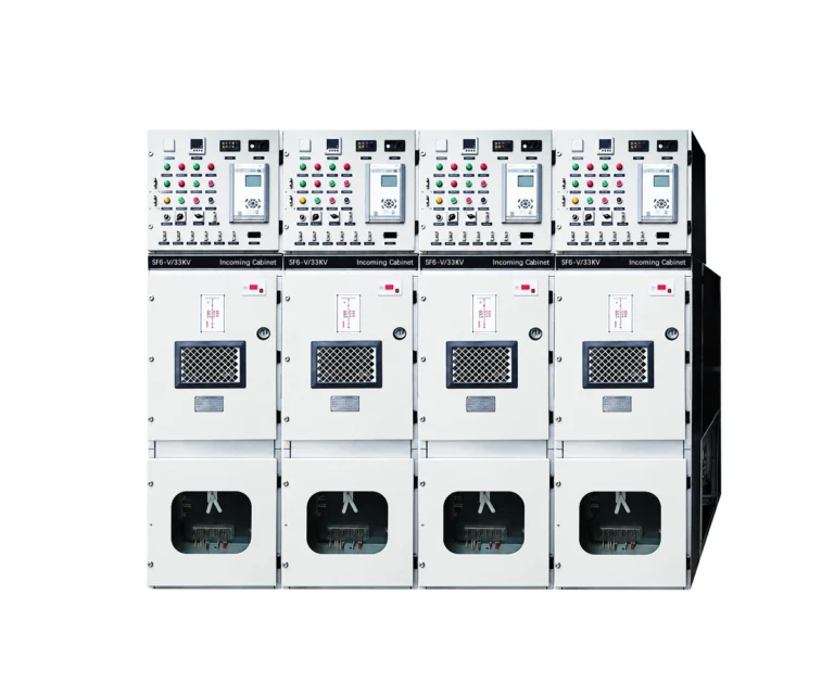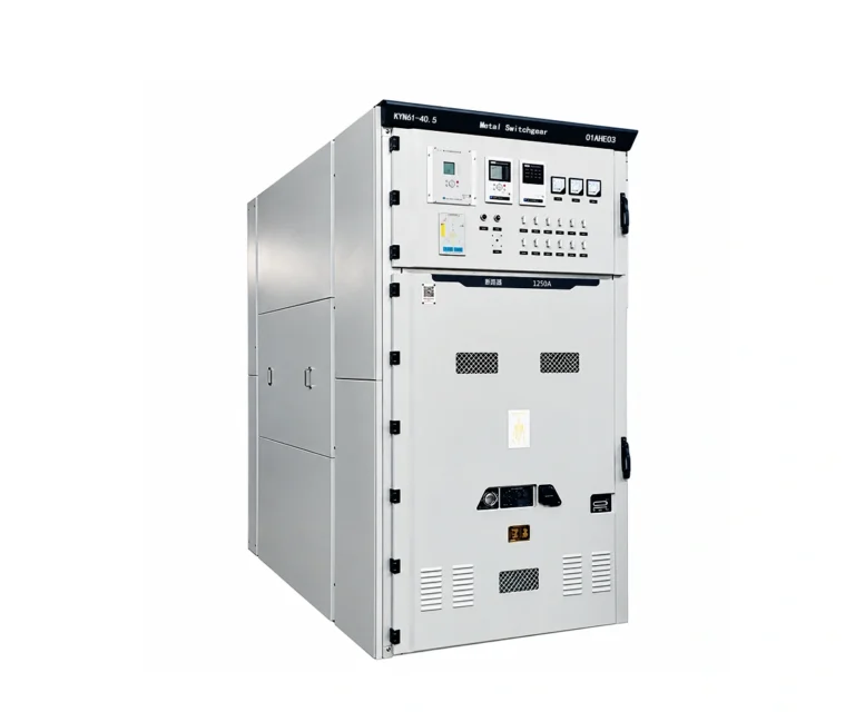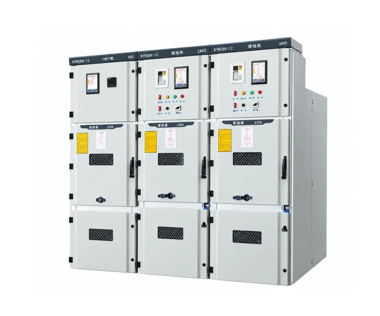
Medium Voltage Equipment / 11 kV Switchgear
Baocheng Electrical
11 kV Switchgear
HXGN□-12ZF(R)
Fixed air-insulated ring main units with vacuum load-break switching. The supplied HXGN document describes a 10 kV network application and a 12 kV maximum operating voltage; 11 kV suitability remains subject to confirmation.
12 kV class · 50 Hz · vacuum load-break switch
630 A · fixed air-insulated RMU
11 kV application — confirmation required

Electrical Characteristics
Nominal system voltage
10 kV (11 kV application subject to confirmation)
Source network / maximum voltage
10 / 12 kV
Rated current
630 A
Short-time withstand
20 kA / 4 s
What Is The HXGN□-12ZF(R)?
HXGN□-12ZF(R) is described as an indoor fixed air-insulated ring main unit with an FZN□-12/630 vacuum load-break switch. Incoming, outgoing and switch-fuse arrangements are selected for the primary circuit.
The supplied text specifies a 10 kV, 50 Hz network; its table labels the voltage as 10 / 12 kV rated / maximum operating voltage. The requested 11 kV title is retained as a review draft, with suitability for an 11 kV system still unconfirmed.
Vacuum load-break switching handles the stated load-current duty. Transformer protection in the outgoing combination depends on the striker-operated fuse arrangement; short-time withstand is not a circuit-breaker short-circuit breaking rating.
Technical Specification Tables
Table 1 — Electrical ratings
| Parameter | Source value |
|---|---|
| Source rated / maximum operating voltage | 10 / 12 kV |
| Rated current / frequency | 630 A / 50 Hz |
| Incoming / outgoing busbar current as listed | 630 A / 125 A |
| Short-time withstand current | 20 kA / 4 s |
| Peak withstand current | 50 kA peak |
| Short-circuit making current | 50 kA peak |
| Active-load breaking current | 630 A |
| Closed-loop breaking current | 630 A |
| Transfer current | 3,150 A |
Source: DOCX embedded technical table. The outgoing 125 A entry is preserved separately from the overall 630 A rating. Cable charging current has an inconsistent unit in the source and is not specified here.
Table 2 — Insulation & mechanical data
| Parameter | Value |
|---|---|
| Power-frequency withstand, 1 min — phases / earth / vacuum LBS gap | 42 kV |
| Power-frequency withstand — isolating gap | 48 kV |
| Lightning impulse withstand — phases / earth / vacuum LBS gap | 75 kV peak |
| Lightning impulse withstand — isolating gap | 85 kV peak |
| Vacuum load-break switch mechanical endurance | 10,000 operations |
| Earthing / isolating switch mechanical endurance | 2,000 operations |
| Enclosure protection in source text | IP2X |
Confirm the complete assembly, component duties and the approved type-test documentation for the proposed network.
Table 3 — Service conditions & arrangement
| Parameter | Value |
|---|---|
| Ambient temperature | −25 to +40 °C |
| Relative humidity — daily / monthly mean | ≤95% / ≤90% |
| Water vapour pressure — daily / monthly mean | ≤2.2 / ≤1.8 kPa |
| Altitude | Requires source clarification |
| Shown cabinet width × depth × height | 850 × 900 × 2,000 mm |
The source altitude entry reads 10,000 m and has not been accepted as a verified capability. Dimensions are those of the supplied example and require configuration confirmation.
HXGN□-12ZF(R): Design & Operating Principle
Functional Overview

This diagram supports the operating description. It is not an approved primary schematic or switching procedure.
01 · Incoming circuit
The incoming arrangement uses vacuum load-break switching and isolation, with an earthing function where specified.
02 · Outgoing protection
The outgoing combination uses a vacuum load-break switch and striker-operated fuses. Fuse selection is coordinated with the protected circuit.
03 · Interlocked interfaces
The source describes mechanical interlocks between switching and earthing positions, with CT / VT and surge-arrester options determined by the scheme.
General Arrangement & Installation Interfaces
Cabinet & Component Arrangement

| Item | Details |
|---|---|
| Shown cabinet dimensions | 850 W × 900 D × 2,000 H mm |
| Identified items | Busbars, bushings, fuse combination, CT and operating mechanism |
This is the source figure, including its original Chinese labels. It illustrates the documented cabinet arrangement, not a confirmed 11 kV project assembly.
Foundation & Room Interfaces

| Item | Details |
|---|---|
| Cabinet interface | Source footprint and bolt slots shown |
| Project approval | Confirm clearances and cable access |
Keep all original dimensions intact. Obtain the approved project foundation drawing before installation; the source drawing alone does not resolve the 11 kV application question.
Applications, Features & Procurement Considerations
Vacuum load-break switching
The document identifies an FZN□-12/630 vacuum load-break switch for the selected ring main unit circuit.
Fixed air-insulated cabinet
Air insulation and a fixed cabinet arrangement organise the incoming, outgoing and secondary functions.
Switch-fuse option
The outgoing combination uses striker-operated fuses with the vacuum load-break switch for the specified protective function.
Configurable secondary devices
CTs, VTs, surge arresters and monitoring components are selected according to the required primary and secondary scheme.
Technical Documents & Supply Scope
HXGN□-12ZF(R) Technical Documents
Original supplied product document, with ratings, configuration information and available drawings. The original source language and annotations are retained.
Inspection & Test Documentation
No independent certification or matching type-test report was provided with this DOCX. Obtain the applicable assembly and component documentation for the selected configuration.
Supply Scope To Confirm
Confirmation of 11 kV system suitability; exact HXGN and FZN variants; circuit functions; fuse coordination; CT / VT ratios; protection; control supply; cable access; corrected service conditions; approved drawings and test records.
Maintenance Planning
The source discusses inspection after accumulated operations, but that interval is not used as a mechanical endurance rating. Follow the approved product operating and maintenance instructions.
11 kV Switchgear FAQ
No. The supplied text describes a 10 kV network and the table states 10 / 12 kV rated / maximum operating voltage. Written confirmation for the intended 11 kV system is needed.
The source identifies a vacuum load-break switch. Do not treat its load breaking duty or short-time withstand as a circuit-breaker fault-breaking rating.
The table lists 630 A overall / incoming and 125 A for the outgoing busbar entry. The selected circuit and fuse arrangement must be clarified; the values have not been merged.
That value appears in the source, but it is unverified and may be an error. This page makes no 10,000 m suitability claim.
Resolve voltage suitability and service conditions, then confirm the exact circuit, switch-fuse selection, fault duty, secondary devices, approved drawings and supply scope.
Related Products
Explore related medium-voltage switchgear and motor starting equipment for power distribution and industrial applications.