Home / SF6 Switchgear / SF6 Load Break Switches / 33KV 36kV SF6 LBS
Baocheng Electrical
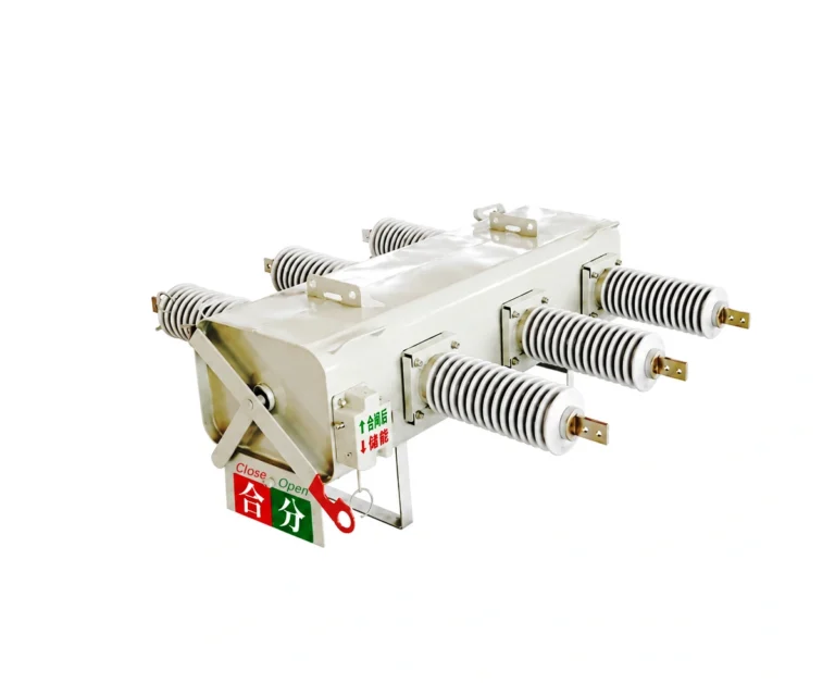
33kV / 36kV (40.5kV) Outdoor Pole-Mounted SF6 Load Break Switch (FLW34-40.5)
Outdoor three-phase SF6-insulated load switching for overhead and cable distribution feeders, with manual operation and optional motorised control.
FLW34-40.5 — 40.5 kV equipment rated voltage
630 A load switching · 50/60 Hz
Outdoor pole-mounted configuration

Electrical Characteristics
Nominal system voltage
33 / 36 / 38 kV
Equipment rated voltage
40.5 kV
Rated current
630 A
Short-time withstand current
20 kA / 4 s
Product Overview
The FLW34-40.5 is a heavy-duty outdoor pole-mounted SF6 load break switch rated for 33kV, 36kV, 38kV,and up to 40.5kV distribution systems (630A). Built with high-creepage porcelain or silicone rubber bushings and a spring-operated mechanism, it ensures safe overhead line switching under harsh climatic conditions.
Column installed insulation load switch, type FLW34-40.5-20,is suitable for the rated voltage 12/24/40.5kV,rated current 400A、630A、50/60Hz power grid open circuit、load current in closed Power system、overload curren. This load switch can separate those broken distribution line automatically.
With the latest technology, it has the newest electronic controller.The switch can be used by manual operation, electric operation and operation from a long distance. Electronic controller is installed in a stainless steel cabinet which is suitable for using under all kinds of climatic conditions. In addition, there are some wired and wireless modem installed in the cabinet through which it can realize the remote monitoring and control. Simple installation on column is convenient, fast, and also can reduce the construction cost.
Technical Specifications and Configuration
Parameter
Specification
Equipment rated voltage
40.5 kV
Nominal-system applications for selection
33 / 36 / 38 kV
Rated frequency
50 / 60 Hz
Rated current
630 A
Rated load-breaking current
630 A
Rated closed-loop breaking current
630 A
Rated short-time withstand current and duration
20 kA / 4 s
Peak withstand current
50 kA
Making current listed in the manual
50 kA
Cable-charging breaking current
25 A
Line-charging breaking current
16 A
Exciting current listed in the manual
21 A
Interruptions at rated current
≥ 400
Mechanical endurance
6000 operations
Gas pressure and insulation levels
Confirm the approved FLW34-40.5 technical schedule
Annual relative gas leakage
≤ 1%
SF6 moisture content at factory handover
≤ 150 ppm
SF6 moisture content in service
≤ 300 ppm
DC operating / auxiliary supply options
220 / 110 / 48 / 24 V
AC operating / auxiliary supply options
220 / 110 V
Mass: M type / A type
135 / 155 kg
Mounting arrangement
Suspended or seated arrangement
Select one operating supply and the required control configuration. Confirm the power-frequency withstand level, creepage distance, enclosure protection and approved connection drawings with the project specification. Gas-pressure settings must match the supplied unit.
Construction and Working Principle
Three-Phase Linked Operation
A common operating mechanism opens and closes the three phases together for distribution feeder switching.
Spring-Stored-Energy Mechanism
The manual describes an over-centre spring mechanism. Stored energy drives contact movement for consistent opening and closing.
Position Indication and Locking
A shaft-linked position indicator shows open and closed status. A manual locking device is described for controlling unintended operation.
Gas-Pressure Supervision
The described low-gas-pressure system provides an alarm and operating lockout. Confirm the pressure settings for the ordered voltage class.
Spring Operating Mechanism

Mechanism illustration from the supplied FLW34 manual. Confirm the selected manual or motor-operated arrangement.
Optional Control Cabinet
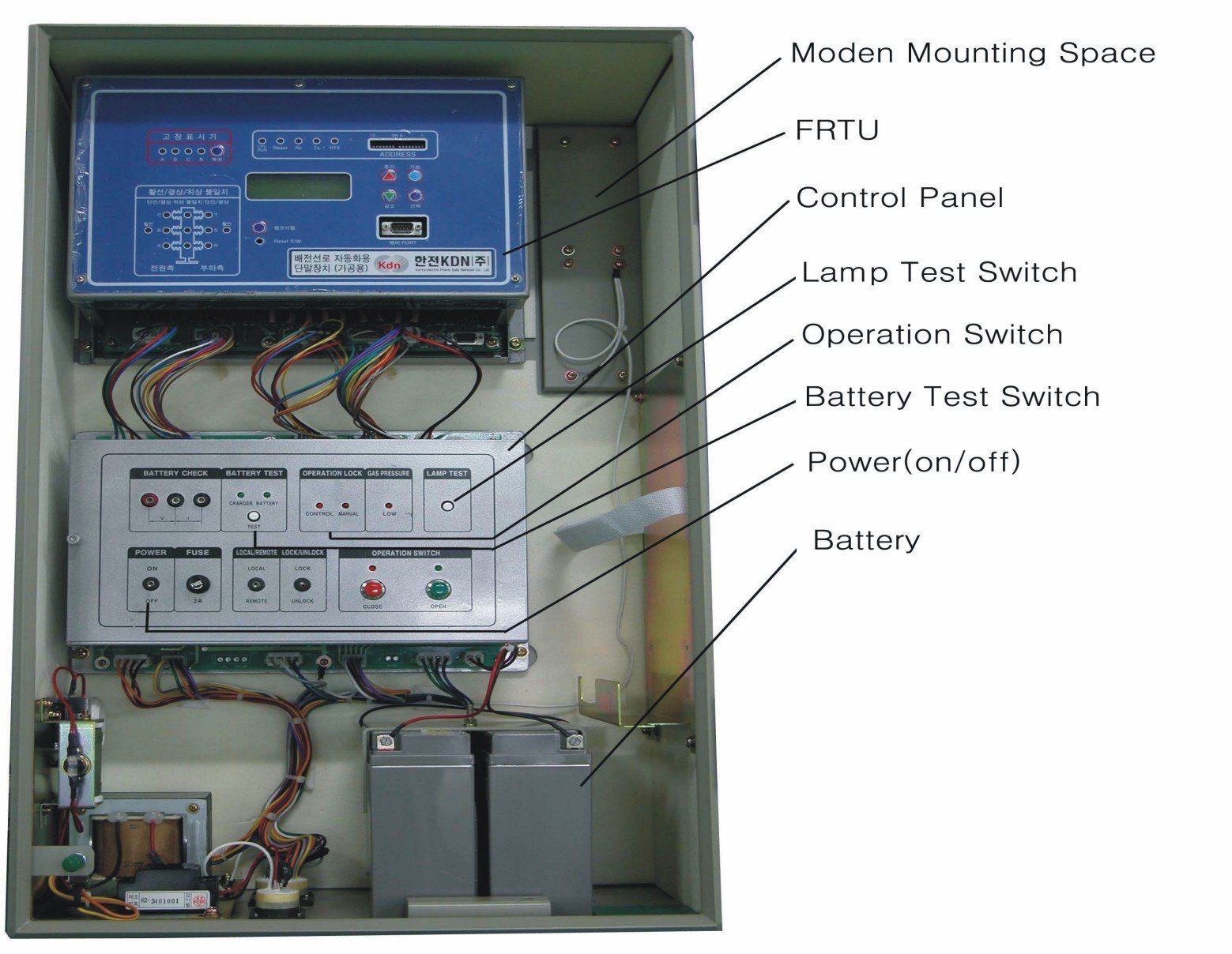
The manual describes local/remote selection, position indication, gas-pressure monitoring and a rechargeable battery arrangement. Communications and controller functions are project options.
Applications and Service Conditions
Overhead Distribution Feeders
Use for load switching and feeder sectionalising in an approved distribution scheme.
Cable and Overhead Interfaces
Select terminal or moulded-cable outlets to suit the conductor arrangement.
Remote Feeder Operation
Specify motor operation and the controller interface when remote supervision and switching are required.
Coordinated Sectionalising
Define the operating sequence with the upstream protective device; the load break switch is not specified here as a fault-interrupting circuit breaker.
Service condition
Manual value
Ambient temperature
−40 °C to +50 °C
Relative humidity
Up to 100%
Standard altitude
Up to 1000 m; higher-altitude configuration by agreement
Wind pressure
Up to 700 Pa
State the site pollution, seismic requirements and installation environment. The manual excludes locations with fire or explosion hazards, chemical corrosion or frequent severe vibration.
Features and Practical Benefits
Pole-Mounted Layout
Suspended and seated arrangements support different pole and bracket layouts.
Terminal and Cable Options
Choose terminal outlets or moulded cables and the required bushing construction.
Local or Remote Operation
Manual operation is described, with motorised and remote-control configurations available for selection.
Clear Switching Status
Mechanical contact-position indication helps identify the switch state from ground level.
Configuration-Based Procurement
Define the voltage class, insulation level, control supply and mounting interfaces before placing an order.
Technical Documents and Supply Scope
Request the approved technical schedule, general arrangement, mounting and terminal drawings, control wiring diagram and operating instructions for the selected FLW34-40.5 configuration.
The manual lists operating instructions, a product conformity document, packing list and factory inspection report as accompanying documents. Confirm the actual document package and the scope of the switch, controller, battery, brackets, bushings, cables and connectors in the quotation.
Technical and Purchasing FAQ
What is the difference between system voltage and rated voltage?
The existing product range identifies 33 / 35 / 36 kV nominal-system applications. The equipment rated voltage is 40.5 kV. Confirm the maximum system voltage, insulation coordination and site conditions for the ordered configuration. The 35 kV application requires confirmation against the approved equipment schedule.
Does 20 kA mean short-circuit breaking capacity?
No. The technical table identifies 20 kA for 4 s as short-time withstand current. The load-breaking current on this page is 630 A. Fault interruption must be addressed by the approved protection scheme.
Can the switch be operated remotely?
The manual describes motor-operated control with an optional electronic controller and FTU interface. Specify the communications interface, control supply and required functions.
Are 400 A and 630 A both available in the manual?
The overview describes both ratings. This page uses the 630 A configuration from the Chinese technical table; confirm any 400 A requirement separately.
Which installation and connection options should be specified?
Specify suspended or seated mounting, terminal or cable outlets, the bushing arrangement, bracket dimensions and conductor interfaces.
What information is needed for a quotation?
Provide the model, quantity, nominal and maximum system voltages, required insulation levels, load and short-time withstand duty, upstream protection, control supplies, site conditions and installation drawings.
Discuss Your FLW34-40.5 Requirements
Send your project specification for a configuration review and quotation. Include the operating voltage, feeder duty, mounting arrangement, control requirements and destination.
Related Products
Explore related SF6 switching and protection equipment for your distribution project.