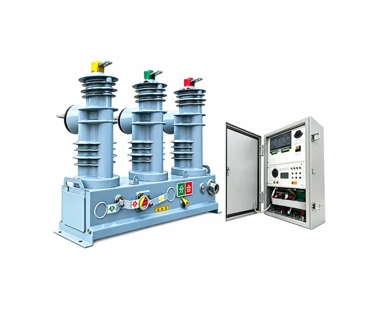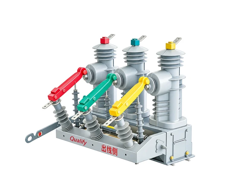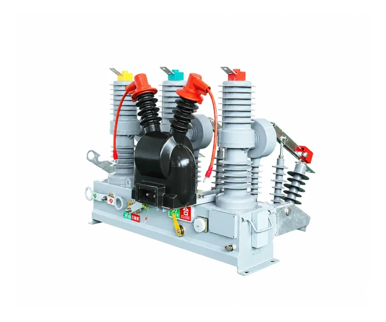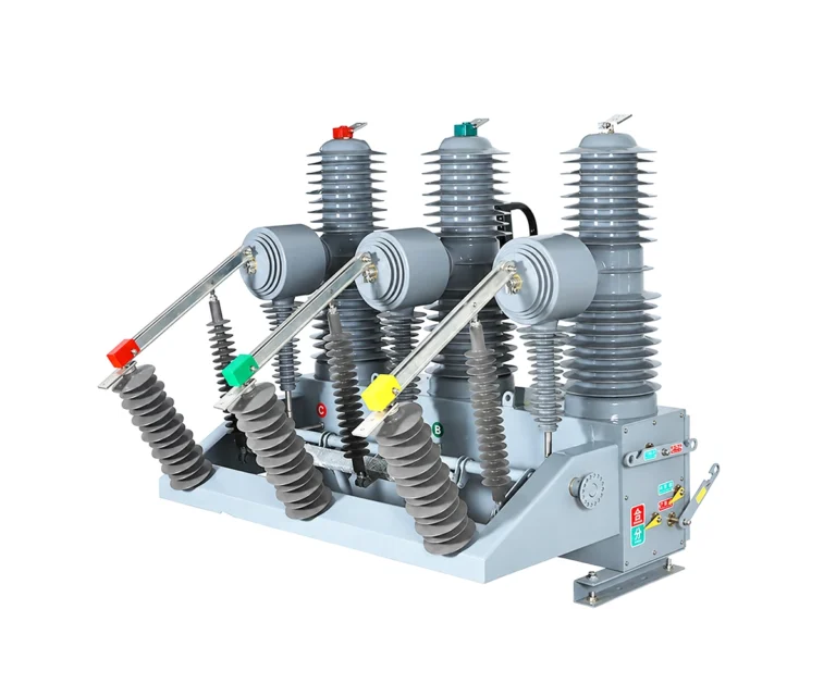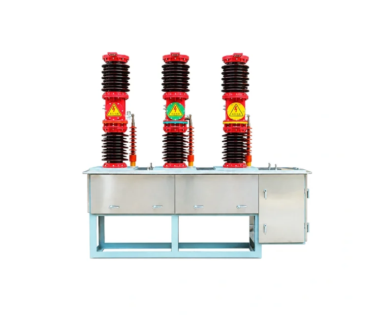
Vacuum Circuit Breakers / 33 KV VCB Breaker
Baocheng Electrical · Technical review draft
33 KV VCB Breaker
ZW7-40.5 · Compact Design
Compact outdoor vacuum switching with a 40.5 kV equipment rating. The ZW7-40.5 combines integrated porcelain-insulated poles, a spring operating mechanism and selectable current transformers for overhead-network switching and protection.
40.5 kV · 1250–2500 A · 25 / 31.5 kA | Outdoor vacuum switching
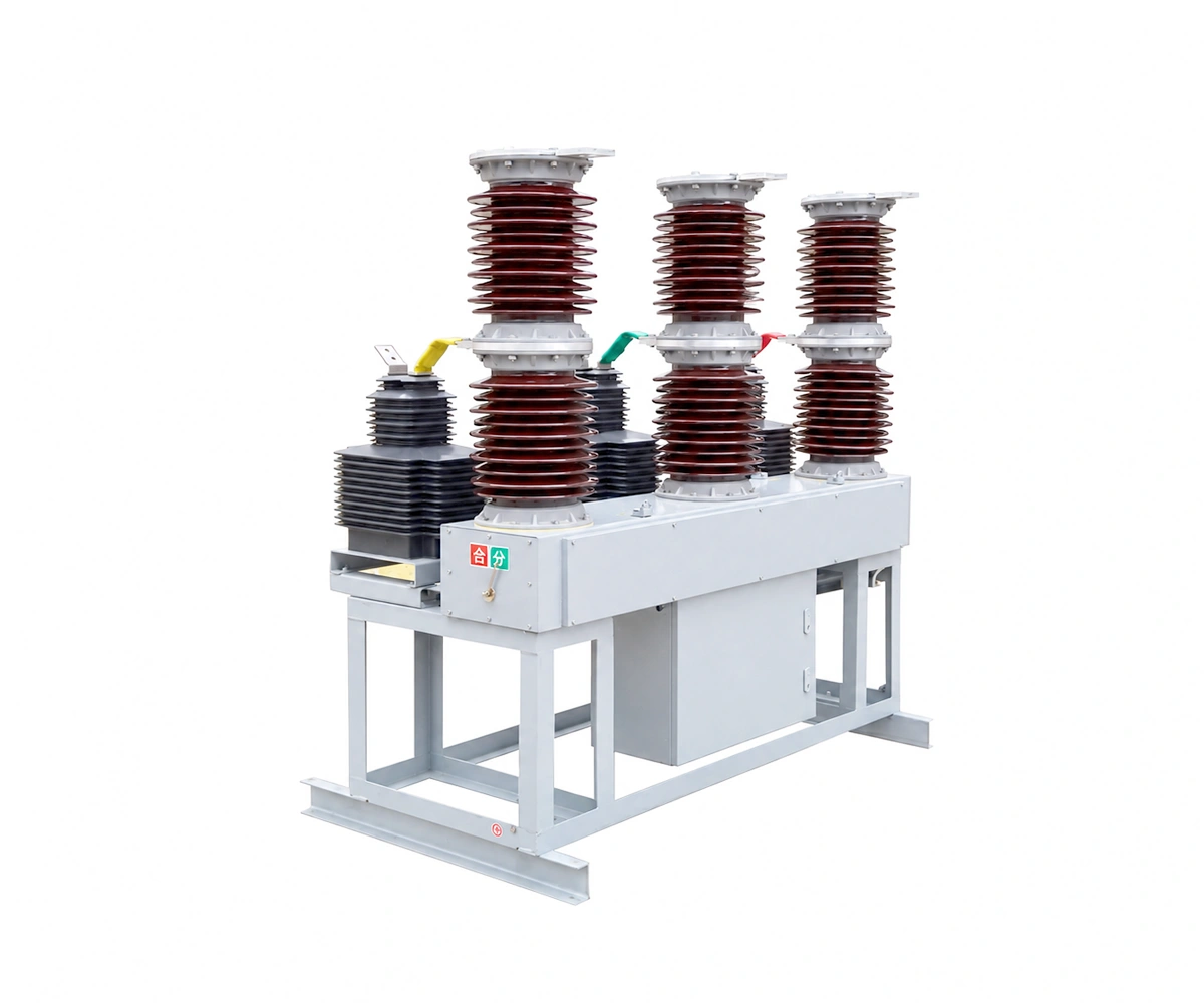
Electrical Characteristics
Nominal system voltage
33 kV (confirm for the selected configuration)
Rated voltage
40.5 kV
Rated normal current
1250–2500 A
Rated short-circuit breaking current
25 / 31.5 kA
About the ZW7-40.5 · Compact Design
The compact ZW7-40.5 outdoor high-voltage vacuum circuit breaker is designed to switch load, overload and short-circuit currents in medium-voltage overhead networks. The assembly combines porcelain-insulated poles, current transformers, an operating mechanism and a stainless-steel enclosure.
33 kV is the product-range designation used on this website. The supplied manual specifies a rated voltage of 40.5 kV. Confirm the network nominal voltage, highest system voltage and required insulation level before selecting the offered configuration.
The manual lists 1250–2500 A and 25 / 31.5 kA without a complete rating-combination matrix. The homepage card lists 2000 A and 31.5 kA; confirm that exact offered combination. This compact version has its own dimensions and approximately 600 kg mass; do not use drawings or ratings from another ZW7 variant.
Technical Specifications — ZW7-40.5 · Compact Design
Electrical Ratings — Manual PDF p. 2
| No. | Parameter | Unit | Value / condition |
|---|---|---|---|
| 1 | Rated voltage | kV | 40.5 |
| 2 | Rated normal current | A | 1250–2500; selected rating to be confirmed |
| 3 | Rated frequency | Hz | 50 or 60 |
| 4 | Rated short-circuit breaking current | kA | 25 / 31.5 |
| 5 | Rated short-circuit making current (peak) | kA | 63 / 80 |
| 6 | Rated peak withstand current | kA | 63 / 80 |
| 7 | Rated short-time withstand current, 4 s | kA | 25 / 31.5 |
| 8 | Operations at rated short-circuit breaking current | operations | 30 |
| 9 | Mechanical endurance | operations | 10,000 |
| 10 | Mechanism control voltage | V | AC 220 or DC 220; confirm selected coils and supply |
| 11 | Secondary-circuit power-frequency withstand voltage, 1 min | kV | 2 |
Insulation & Operating Sequence — Manual PDF p. 2
| No. | Parameter | Unit | Value / condition |
|---|---|---|---|
| 1 | Power-frequency withstand voltage, 1 min | kV | 80 / 90 / 95; wet/dry and phase-to-phase, phase-to-earth/across-open-contacts assignments require confirmation |
| 2 | Lightning impulse withstand voltage (peak) | kV | 185; confirm application to phase-to-phase, phase-to-earth and across open contacts |
| 3 | Rated operating sequence, as printed | — | O – 0.1 s – CO – 3 s – CO – 6 s – CO; 60 s recovery stated. Confirm the approved duty and controller settings |
Mechanical Characteristics — Manual PDF p. 3
| No. | Parameter | Unit | Value / condition |
|---|---|---|---|
| 1 | Contact gap | mm | 22 ± 2 |
| 2 | Contact overtravel | mm | 4 ± 0.5 |
| 3 | Opening speed | m/s | 1.4–1.8 |
| 4 | Closing speed | m/s | 0.4–0.8 |
| 5 | Contact bounce during closing | ms | ≤ 5 |
| 6 | Phase centre distance | mm | 700 (800) ± 2; illustrated arrangement: 700 |
| 7 | Opening and closing time discrepancy between poles | ms | ≤ 2 |
| 8 | Main circuit resistance per phase | μΩ | ≤ 80 |
| 9 | Closing time | ms | ≤ 100 |
| 10 | Opening time | ms | ≤ 50 |
| 11 | Mass | kg | Approximately 600 |
Service & Storage Conditions — Manual PDF p. 2
| No. | Parameter | Unit | Value / condition |
|---|---|---|---|
| 1 | Ambient air temperature | °C | −30 to +60 |
| 2 | Installation altitude | m | ≤ 3000 |
| 3 | Wind speed | m/s | ≤ 34 |
| 4 | Pollution severity | — | Class IV, as stated in the manual; confirm project applicability |
| 5 | External vibration and earth tremors | — | Negligible, as specified in the manual |
| 6 | Storage temperature | °C | −40 to +85 |
Illustrated Installation Dimensions — Manual PDF pp. 3, 5
| No. | Parameter | Unit | Value / condition |
|---|---|---|---|
| 1 | Overall breaker width | mm | 1700, PDF p. 3 |
| 2 | Breaker assembly height | mm | 2000, PDF pp. 3 and 5 |
| 3 | Side-view base dimension | mm | 782, PDF p. 3 |
| 4 | Mounting-slot callout | mm | 8 slots, 25 × 40, PDF p. 3 |
| 5 | Illustrated installed height | mm | 3200, PDF p. 5 |
| 6 | Additional installation support height | mm | 1200, PDF p. 5; not the breaker-only height |
| 7 | Dry arcing distance | mm | 413, PDF p. 5; not a creepage-distance value |
ZW7-40.5 · Compact Design: Design & Operating Principle
Compact Pole & Enclosure Arrangement
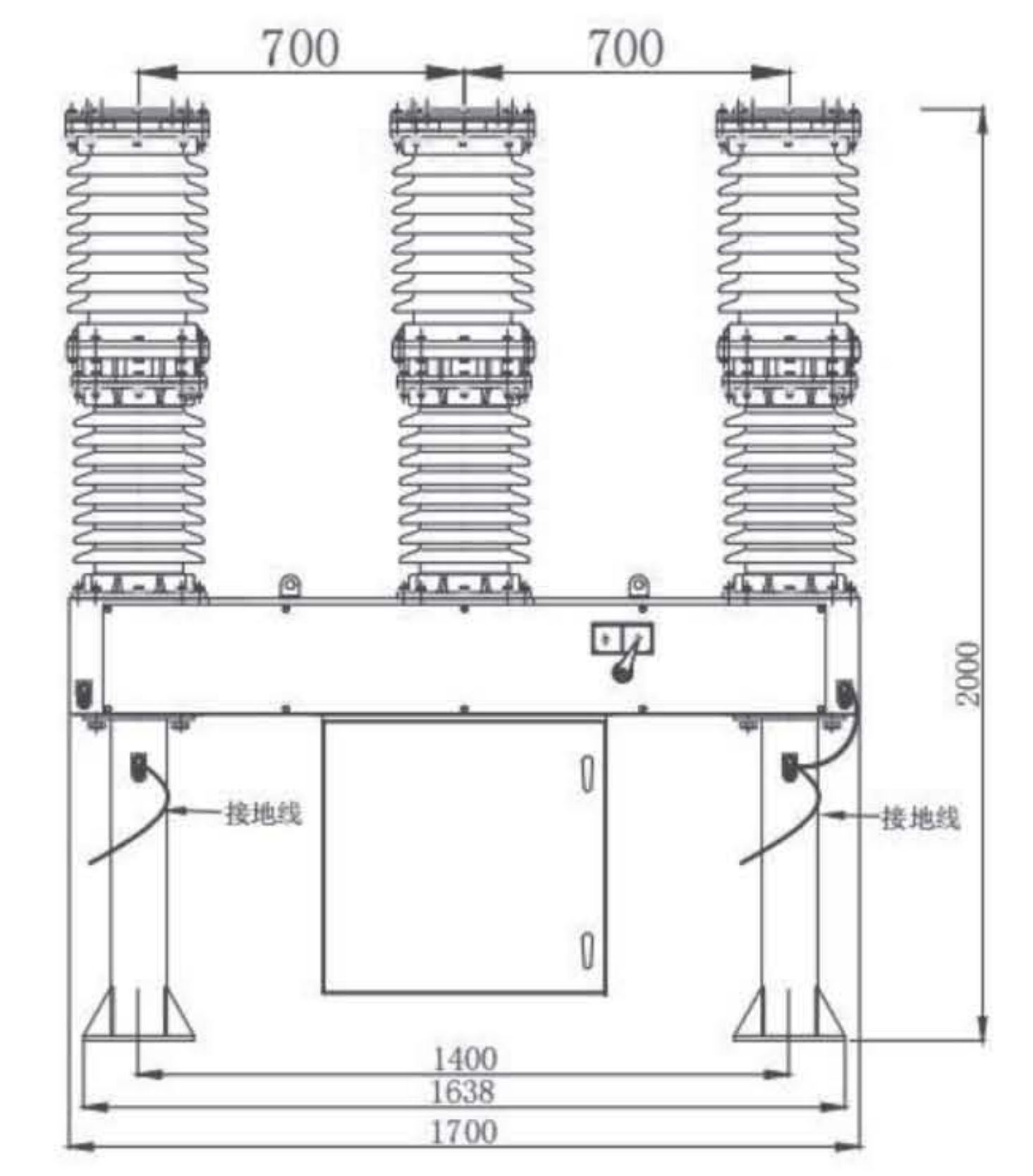
Front-view detail from the supplied manual, PDF p. 3. This is an external arrangement drawing, not an internal mechanism cutaway.
Integrated porcelain-insulated poles sit above the stainless-steel enclosure and support structure. The manual identifies current transformers as selectable equipment; confirm the ratio, accuracy class, burden and supplied arrangement separately.
01 Spring Charging
The motor drives the charging gear train to store energy in the closing spring. A travel switch interrupts the motor supply when charging is complete. The manual also describes manual spring charging.
02 Closing & Tripping
Closing and opening electromagnets release the corresponding latches. The stored spring energy drives the linkage and contacts. Manual operation and an overcurrent release are described in the manual; confirm the supplied mechanism configuration.
03 Vacuum Interruption
When the contacts separate, an arc forms inside the vacuum interrupter. The axial magnetic field helps distribute the arc across the contact surfaces. At natural current zero, dielectric strength recovers across the open contact gap.
Control & Communication Options
With a matching intelligent controller, the breaker can support local operation, remote commands and status transmission. The manual mentions cable, optical fibre and GPRS/CDMA/GSM channels; confirm the actual controller, protocol and available communications service for the project.
Drawings & Installation Interfaces
Review the supplied drawings for the selected arrangement. Select an image to inspect the full-size original; confirm the approved project revision before installation.
Compact ZW7-40.5 — General Arrangement

| Phase centres shown: 700 mm |
| Breaker height: 2000 mm |
| Overall width: 1700 mm |
| Mounting slots: 8 × (25 × 40 mm) |
Front, side and mounting views are reproduced from PDF p. 3. The mechanical table also lists an 800 mm phase-spacing option; the illustrated drawing shows 700 mm. Match the dimensions to the approved equipment configuration before preparing supports.
Support & Foundation — Installation Arrangement

| Installed height shown: 3200 mm |
| Additional support height: 1200 mm |
| Front support spacing: 1400 mm |
| Dry arcing distance callout: 413 mm |
The installation sketch on PDF p. 5 shows the breaker on additional supports above a foundation. The 3200 mm installed height includes the 1200 mm support arrangement. This sketch is not a foundation design calculation; confirm anchor bolts, loads and civil details on the approved project drawing.
Applications, Features & Procurement Considerations
The compact ZW7-40.5 outdoor high-voltage vacuum circuit breaker is designed to switch load, overload and short-circuit currents in medium-voltage overhead networks. The assembly combines porcelain-insulated poles, current transformers, an operating mechanism and a stainless-steel enclosure.
Compact Assembly
Approximately 600 kg, with a compact arrangement and stainless-steel enclosure described in the manual.
Vacuum Interruption
Integrated porcelain-insulated poles with vacuum interrupters and axial-magnetic-field arc control.
Spring Operation
Motor and manual spring charging are described; the listed mechanical endurance is 10,000 operations.
Selectable Current Transformers
Current transformers can be selected to suit the user requirement. Ratios and core specifications require an agreed data sheet.
Local & Remote Control
A matching intelligent controller can provide local operation, remote commands and status transmission.
Technical Documents & Supply Scope
ZW7-40.5 · Compact Design Technical Documents
Request the technical package for the selected configuration:
- Approved electrical ratings and model designation.
- General arrangement and mounting drawings.
- Controller wiring and current/voltage sensing details.
- Installation and maintenance instructions.
Inspection & Test Documentation
Request model-specific routine test records and any type-test evidence required by the project. The supplied reference manual alone does not establish certification for the offered equipment.
The supplied manual does not identify a compliance standard or provide test reports. Agree the applicable standard edition and request evidence covering the offered configuration.
Supply Scope to Confirm
- Exact model, ratings and number of units.
- Operating mechanism and auxiliary supply.
- Current/voltage transformers and controller options.
- Disconnectors, supports, cables and accessories.
- Site conditions and approved installation interfaces.
Identify included and excluded equipment explicitly. Confirm that the supplied drawings and controller configuration correspond to the ordered unit.
Maintenance Planning
The manual describes maintenance-free operation without defining its scope or exclusions. Confirm routine inspections and the maintenance requirements for the operating mechanism, controller, connections and installed assembly.
Send the network voltage, load current, prospective fault current, control supply, site conditions and required installation arrangement with your inquiry.
33 KV VCB Breaker FAQ
Why does this 33 kV product page show a 40.5 kV rated voltage?
33 kV is the website product-range designation. The supplied ZW7-40.5 manual gives a 40.5 kV equipment rated voltage. Verify system voltage and insulation coordination for the intended project; do not relabel the equipment rated voltage as 33 kV.
Which current and breaking ratings are available?
The manual lists rated normal current from 1250 to 2500 A and rated short-circuit breaking current of 25 or 31.5 kA. It does not provide a complete combination matrix. Confirm the exact combination and corresponding test evidence in the offer.
How is this compact ZW7 different from another ZW7-40.5?
This manual lists approximately 600 kg mass, a 2000 mm breaker assembly height and a 1700 mm overall width in the illustrated arrangement. Its operating mechanism details, dimensions and ratings must be checked independently of other ZW7 versions.
Are the controller and current transformers included?
The manual describes selectable current transformers and operation with a matching intelligent controller. It does not define a fixed commercial supply package. Confirm CT specifications, controller model, communication interfaces, auxiliary supply and included cables in the quotation.
What site conditions and installation drawings apply?
The manual states −30 to +60 °C ambient temperature, altitude up to 3000 m, wind speed up to 34 m/s and pollution class IV. It expects negligible external vibration or earth tremors. Confirm the selected 700 or 800 mm phase spacing and approved support/foundation design.
Which technical items should be confirmed before ordering?
Confirm rating combinations, the 80 / 90 / 95 kV power-frequency withstand assignments, the printed operating sequence, controller and CT options, auxiliary supply and site conditions. The manual states maintenance-free operation but does not define its exclusions; agree inspection and maintenance requirements for the delivered assembly.
Related Products
Explore related vacuum circuit breakers for medium-voltage power distribution and protection applications.