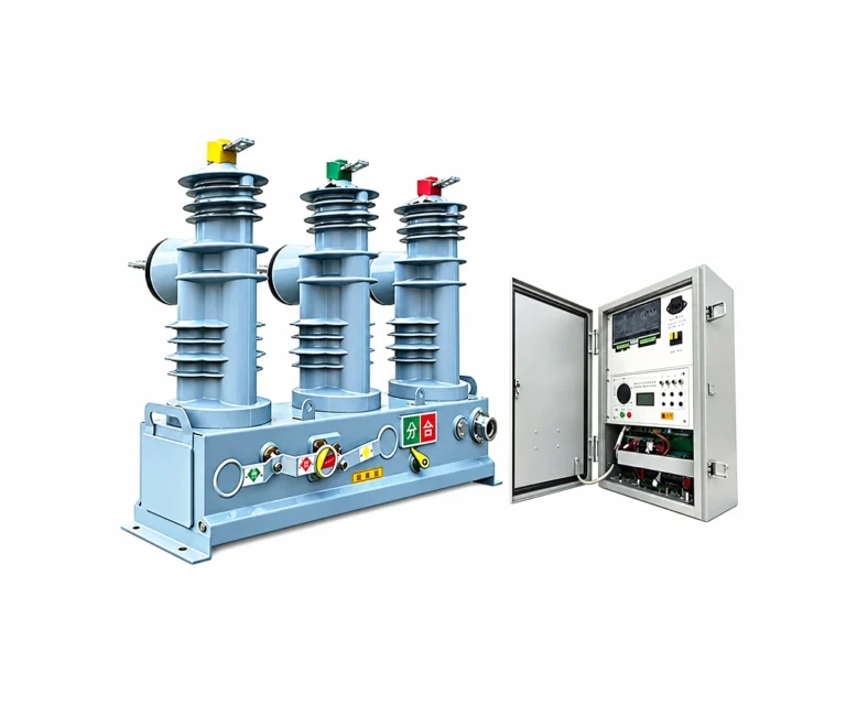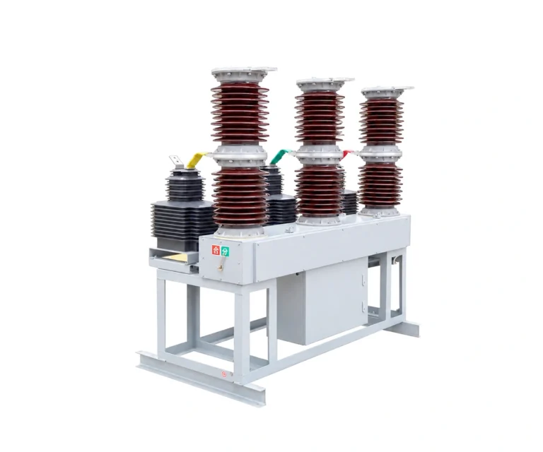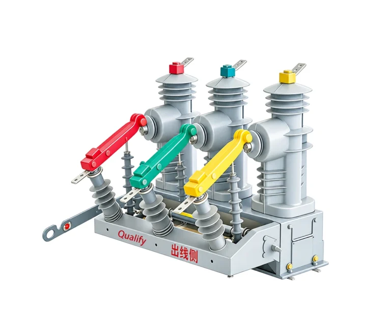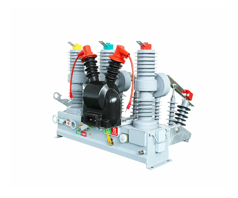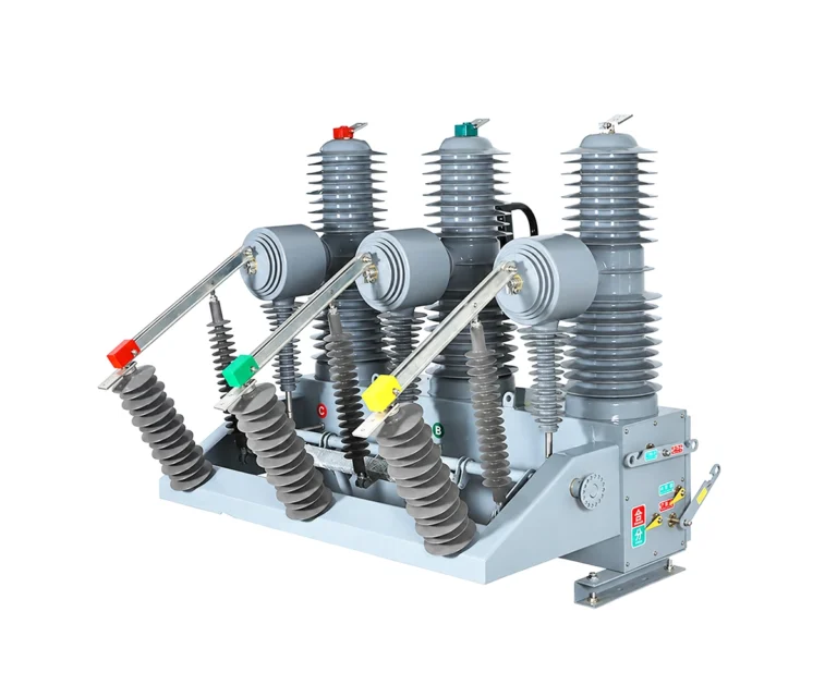
Vacuum Circuit Breakers / VCB Circuit Breaker
Baocheng Electrical
VCB Circuit Breaker
ZW7-40.5
Outdoor vacuum switching for 35 kV power systems. A 40.5 kV equipment rating, CT19BW spring mechanism and configurable current transformers support load switching and fault interruption in three-phase 50 Hz networks.
40.5 kV Rated Voltage · 35 kV System
1600 / 2000 A · 20 / 25 / 31.5 kA options
Outdoor Installation · Three-Phase · 50 Hz
Electrical Characteristics
Nominal system voltage
35 kV
Rated voltage
40.5 kV
Rated normal current
1600 / 2000 A
Rated short-circuit breaking current
20 / 25 / 31.5 kA
What Is the ZW7-40.5 VCB Circuit Breaker?
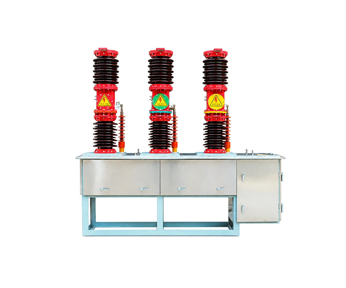
The ZW7-40.5 is an outdoor AC high-voltage vacuum circuit breaker for 35 kV distribution and substation switching duties. Its porcelain-insulated pole arrangement houses the vacuum interrupters above a operating mechanism enclosure containing the three-phase linkage and current transformers.
35 kV system voltage and 40.5 kV equipment rating are different specifications. Use both values when preparing an inquiry. Select the rated normal current, short-circuit duty, control voltage and current-transformer arrangement together for the offered unit.
The manual presents multiple electrical configurations. Its table groups 1600 A with the 20 / 25 kA columns and 2000 A with the 31.5 kA column. Confirm the exact rating combination in the technical quotation; the listed options do not imply that every combination is available.
Technical Specification Tables for ZW7-40.5
Table 1 – Main Electrical Parameters
| No. | Parameter | Unit | Value |
|---|---|---|---|
| 01 | Rated voltage | kV | 40.5 |
| 02 | Nominal system voltage | kV | 35 |
| 03 | Rated frequency | Hz | 50 |
| 04 | Rated normal current | A | 1600 / 2000 |
| 05 | Rated short-circuit breaking current | kA | 20 / 25 / 31.5 |
| 06 | Rated short-circuit making current (peak) | kA | 50 / 63 / 80 |
| 07 | Rated short-time withstand current | kA | 20 / 25 / 31.5 |
| 08 | Rated peak withstand current | kA | 50 / 63 / 80 |
| 09 | Rated duration of short circuit | s | 4 |
| 10 | Rated operating sequence | — | O – 0.3 s – CO – 180 s – CO |
| 11 | 1 min power-frequency withstand voltage, dry | kV | 95 |
| 12 | 1 min power-frequency withstand voltage, wet | kV | 80 |
| 13 | Rated lightning impulse withstand voltage (peak) | kV | 185 |
| 14 | Rated operating voltage options | V | AC 220 / 110; DC 220 / 110 |
| 15 | Operations at rated short-circuit breaking current | operations | 20 |
| 16 | Mechanical endurance | operations | 10,000 |
Table 2 – Mechanical Characteristics
| No. | Parameter | Unit | Value |
|---|---|---|---|
| 01 | Operating mechanism | — | CT19BW spring operating mechanism |
| 02 | Contact gap | mm | 20 (+3 / -2) |
| 03 | Contact overtravel | mm | 5 ± 1 |
| 04 | Average opening speed | m/s | 1.4–1.8 |
| 05 | Average closing speed at rated closing voltage | m/s | 0.4–0.8 |
| 06 | Contact bounce during closing | ms | ≤ 5 |
| 07 | Closing time discrepancy between poles | ms | ≤ 2 |
| 08 | Opening time (mechanical table) | ms | 40–100 |
| 09 | Closing time | ms | 50–150 |
| 10 | Closing operating voltage, maximum / minimum | V | 242 / 187 (listed in the mechanical table; confirm selected coil) |
| 11 | Main circuit resistance per phase, excluding current transformer | μΩ | ≤ 120 |
| 12 | Phase centre distance | mm | 710 |
| 13 | Permissible cumulative contact wear | mm | 3 |
| 14 | Contact spring force in closed position | N | 2500 / 3000, configuration dependent |
| 15 | Mass | kg | 1100 |
Opening-time figures are reproduced from the mechanical-characteristics table. The main technical table separately lists total breaking time ≤ 80 ms; confirm the applicable timing specification for the selected configuration.
Table 3 – Current Transformer Cores
| No. | Parameter | Unit | Value |
|---|---|---|---|
| 01 | 1S: metering or measuring | VA / class | 15 / 0.2 |
| 02 | 2S: monitoring or measurement | VA / class | 25 / 0.5 |
| 03 | 3S: protection | VA / class | 50 / 10P10 |
| 04 | 4S: protection | VA / class | 50 / 10P10 |
The manual describes two-, three- or four-core current-transformer arrangements per phase. Confirm the required ratio, core count, accuracy and burden in the order.
Table 4 – Current Transformer Thermal and Dynamic Ratings
| No. | Parameter | Unit | Value |
|---|---|---|---|
| 01 | Primary 75–150 A; secondary 5 A | thermal / dynamic | 60 × I1n / 150 × I1n |
| 02 | Primary 150–300 A; secondary 5 A | kA / kA peak | 9 / 23 |
| 03 | Primary 300–400 A; secondary 5 A | kA / kA peak | 16 / 40 |
| 04 | Primary 600–800 A; secondary 5 A | kA / kA peak | 20 / 50 |
| 05 | Primary 1000–1500 A; secondary 5 A | kA / kA peak | 31.5 / 80 |
| 06 | Primary 1500–2000 A; secondary 5 A | kA / kA peak | 40 / 100 |
Thermal ratings refer to 4 s rms current; dynamic ratings are peak values. I1n denotes rated primary current. These are current-transformer ratings, not the breaker’s short-circuit breaking capacity.
Table 5 – Service Conditions
| No. | Parameter | Unit | Value |
|---|---|---|---|
| 01 | Normal ambient temperature | °C | -30 to +40 |
| 02 | Cold-region version | °C | Down to -40; specify at ordering |
| 03 | Installation altitude | m | ≤ 2000; higher-altitude version above 2000 |
| 04 | Wind pressure | Pa | ≤ 700 (manual equivalent wind speed: 34 m/s) |
| 05 | Pollution conditions | — | Class III; anti-pollution version Class IV, as described in the manual |
| 06 | Installation environment | — | No fire or explosion hazard, chemical corrosion or severe vibration |
ZW7-40.5 Vacuum Circuit Breaker: Design & Operating Principle
Interrupter & Linkage View
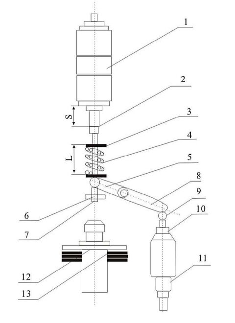
Mechanism drawing from the product manual. Select the drawing to inspect the numbered parts.
Drawing key: 1 vacuum interrupter; 4 contact spring; 7 guide rod; 11 insulating pull rod; 12 oil buffer.
01 Spring Mechanism & Trip Command
The CT19BW spring mechanism drives the operating linkage. Coordinate the closing and trip circuits with the selected AC or DC operating-voltage configuration and the project protection scheme.
02 Contact Movement
The mechanism moves the insulating pull rod and crank linkage, driving the moving contact inside each vacuum interrupter. The linkage controls the contact gap and overtravel.
03 Vacuum Interruption
As the contacts separate, the switching arc is confined to the vacuum interrupter and extinguishes at current zero. The open contact gap then provides dielectric separation; the required breaking duty must match the selected rating.
Mechanism & Auxiliary Control Interface
CT19BW spring mechanism · AC 220 / 110 V or DC 220 / 110 V options. The enclosure includes moisture-control measures and a heater. Confirm coil voltages, wiring and current-transformer terminals against the supplied unit’s documents.
General Arrangement & Installation Interfaces
Review the mounting arrangement and foundation drawings for the selected breaker version. The manual includes both standard and middle-mounted arrangements.
40.5 KV Outdoor Vacuum Circuit Breaker — General Arrangement
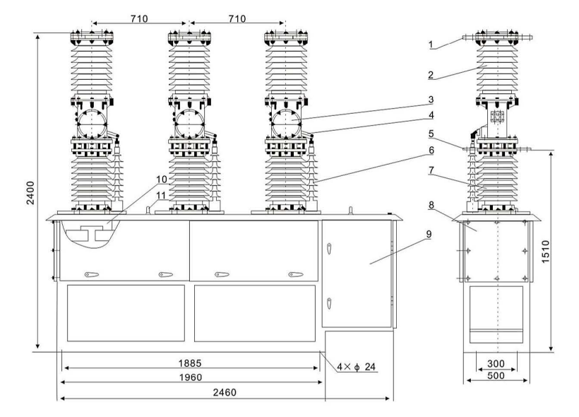
| Arrangement: standard outdoor version |
| Phase centres: 710 mm |
| Overall length shown: 2460 mm |
| Drawing height: 2400 mm |
Front and side views show the standard ZW7-40.5 arrangement. The manual lists a different overall height in its data table; confirm the approved project drawing before preparing the foundation or installation.
Foundation & Support — Installation Interfaces
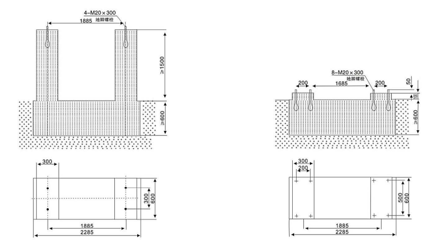
| Left detail: without support frame |
| Right detail: with support frame |
| Application: standard arrangement |
| Confirm the selected mounting configuration |
The manual provides separate foundation details for installation with and without a support frame. Match the foundation to the ordered arrangement and confirm the approved mounting dimensions before civil works.
Applications, Features & Procurement Considerations
Use this breaker for outdoor switching and protection in 35 kV networks, including substation projects and replacement projects for older outdoor oil circuit breakers. For retrofit work, provide the existing installation dimensions.
35 kV Switching Duty
For load, overload and short-circuit current switching in three-phase 50 Hz networks.
Vacuum Interrupters
Vacuum interruption with a porcelain-insulated outdoor pole arrangement.
Spring Operation
CT19BW spring mechanism; the manual lists 10,000 mechanical operations.
Metering & Protection
Selectable current-transformer cores for measurement, monitoring and protection.
Outdoor Site Selection
Check temperature, altitude, wind and pollution conditions before ordering.
Technical Documents & Supply Scope
ZW7-40.5 Technical Documents
Request the technical package for the selected configuration:
- Approved electrical and mechanical data sheet.
- General arrangement and foundation drawings.
- Control wiring and current-transformer details.
- Installation, operation and maintenance instructions.
Inspection & Test Documentation
The manual lists a product conformity certificate, installation manual, mechanism manual and document packs for the current transformers and vacuum interrupters. Request model-specific test evidence needed for project approval.
The supplied manual cites GB 1984-2003 and IEC 62271-100:2001. Agree the required standard edition and supporting reports for the offered equipment; these manual references are not a claim of current third-party certification.
Supply Scope to Confirm
- Breaker rating combination and quantity.
- Spring mechanism and operating voltage.
- Current-transformer ratios, cores, accuracy classes and burdens.
- Support frame requirement and height.
- Wiring interfaces, accessories and project spares.
- Inspection, packing and delivery requirements.
For retrofit orders, include the original equipment’s mounting dimensions. Identify included and excluded items separately in the quotation.
Maintenance Planning
The manual calls for routine checks, an annual minor inspection and a major inspection every five years. Confirm the maintenance plan for the site and operating duty; this equipment is not presented as maintenance-free.
Send the required system voltage, breaker ratings, control supply, CT specification, site conditions and mounting arrangement with your inquiry.
VCB Circuit Breaker FAQ
Is this a 35 kV or a 40.5 kV circuit breaker?
The application is a 35 kV system; the rated voltage in the manual is 40.5 kV. The manual identifies the product as ZW7-40.5. State both the network voltage and equipment rating in your specification.
Which current and breaking-current combinations are listed?
The manual groups 1600 A with 20 / 25 kA, and 2000 A with 31.5 kA. Confirm the offered combination in the quotation. A rating shown on a general product-range page should not replace the selected model data sheet.
What operating mechanism and control voltage are used?
The manual specifies a CT19BW spring operating mechanism and lists AC 220 / 110 V and DC 220 / 110 V operating-voltage options. Confirm the coil and auxiliary-circuit voltages for the selected unit before wiring.
Which outdoor service conditions should I specify?
The normal ambient range is -30 to +40 °C, with a cold-region version down to -40 °C. The reference altitude is up to 2000 m; higher sites require the appropriate version. Include wind, pollution and any corrosive or vibration conditions in the inquiry.
Are current transformers and the support frame fixed configurations?
No. The manual describes configurable current-transformer ratios and two-, three- or four-core arrangements per phase. The support frame and height must also be specified. Confirm the complete supply scope in the quotation.
What information is needed for a quotation?
Provide the product name, rating combination, quantity, CT ratios and accuracy requirements, operating voltage, site conditions, support-frame requirement and installation dimensions. For retrofit projects, include the existing equipment drawings.
Related Products
Explore related vacuum circuit breakers for medium-voltage power distribution and protection applications.