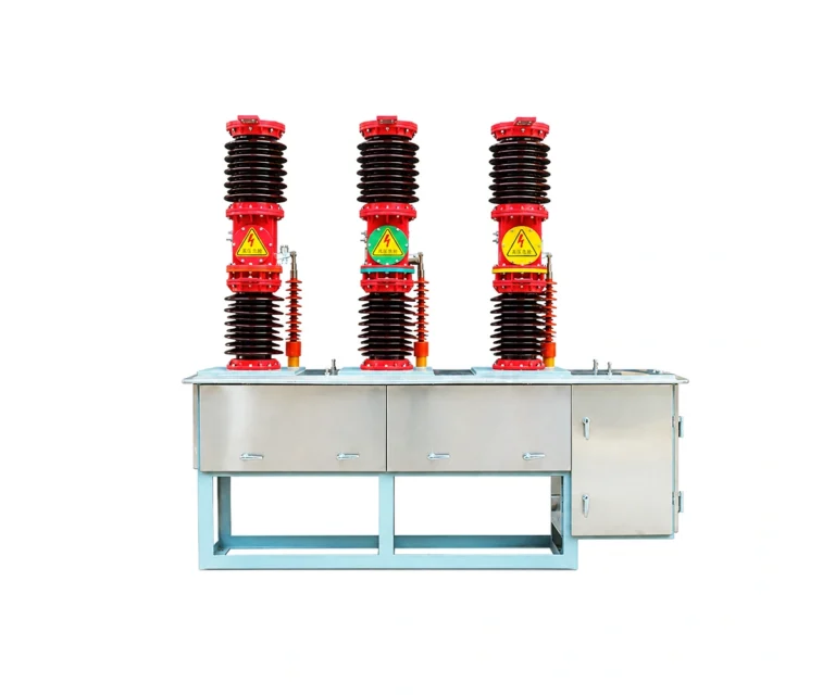
Vacuum Circuit Breakers / Outdoor VCB Breaker
Baocheng Electrical · Technical review draft
Outdoor VCB Breaker
ZW32-12 · High Altitude
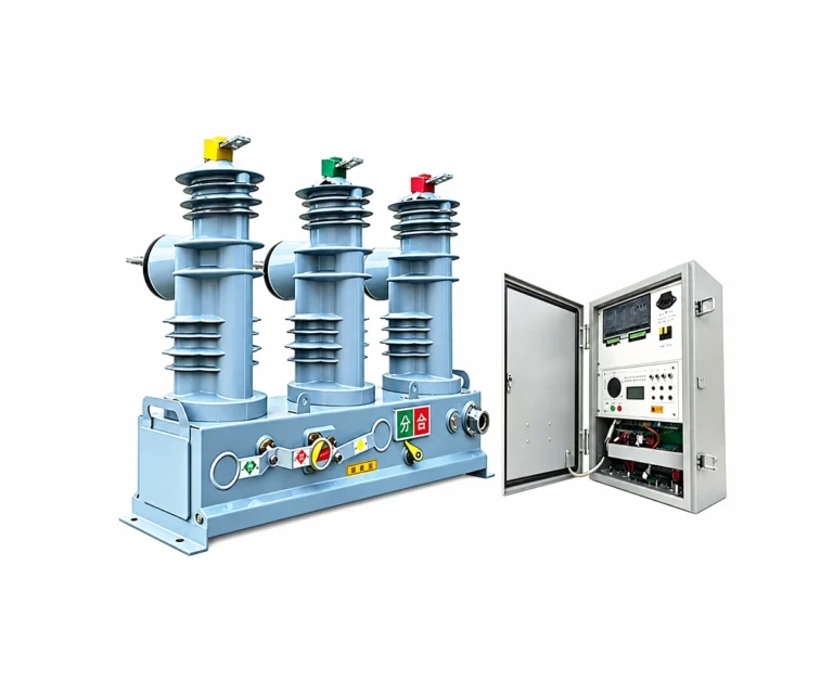
A high-altitude ZW32-12 outdoor breaker arrangement with a disconnector and a spring-mechanism controller interface. The supplied engineering sheets define the installation geometry and FTU connections for project review.
12 kV · To be confirmed · To be confirmed | Outdoor vacuum switching
Electrical Characteristics
Nominal system voltage
10 / 11 kV
Rated voltage
12 kV
Rated normal current
To be confirmed
Rated short-circuit breaking current
To be confirmed
About the ZW32-12 · High Altitude
The supplied two-sheet document covers a ZW32-12 high-altitude arrangement and an FTU controller connection diagram. It is an interface drawing package rather than a complete electrical data sheet.
The drawing title identifies an altitude of up to 4000 m. This is a drawing-specific designation; confirm the complete assembly insulation level and site conditions before selection.
Technical review draft: rated normal current, short-circuit breaking capacity and insulation test levels are not established by these drawings. Request the matching approved data sheet.
Technical Specifications — ZW32-12 · High Altitude
Product identification — drawing 1
| No. | Parameter | Unit | Value / condition |
|---|---|---|---|
| 1 | Equipment voltage designation | kV | 12 |
| 2 | Drawing altitude designation | m | ≤ 4000 |
| 3 | Rated normal current | A | To be confirmed |
| 4 | Rated short-circuit breaking current | kA | To be confirmed |
General arrangement — drawing 1
| No. | Parameter | Unit | Value / condition |
|---|---|---|---|
| 1 | Phase centres | mm | 380 ± 2 |
| 2 | Overall length shown | mm | 1020 |
| 3 | Overall height shown | mm | 880 |
| 4 | Side-view depth shown | mm | 550 |
Mounting interface — drawing 1
| No. | Parameter | Unit | Value / condition |
|---|---|---|---|
| 1 | Mounting centres | mm | 1000 × 160 |
| 2 | Mounting slots | mm | 4 × 13 × 18 |
| 3 | Terminal plate width shown | mm | 40 |
| 4 | Terminal holes shown | mm | 2 × Ø13 |
Controller interface — drawing 2
| No. | Parameter | Unit | Value / condition |
|---|---|---|---|
| 1 | Controller connection | — | 20-pin H connector |
| 2 | Mechanism | — | Spring stored-energy |
| 3 | Motor and coil circuits shown | — | 220 V AC |
| 4 | Digital-input common shown | — | 24 V + |
| 5 | VT supply connector | — | 2-pin K, 220 V AC secondary |
Engineering data to confirm
| No. | Parameter | Unit | Value / condition |
|---|---|---|---|
| 1 | Insulation withstand levels | — | Request matched high-altitude data sheet |
| 2 | Temperature and pollution conditions | — | Confirm project requirements |
| 3 | Current-transformer arrangement | — | Confirm phase / zero-sequence inputs |
| 4 | Transformer alarm connectors | — | Optional B1 / B2 interfaces |
ZW32-12 · High Altitude: Design & Operating Principle
Disconnector & Pole — Drawing Detail

Side-view detail extracted from drawing 1; original geometry is retained.
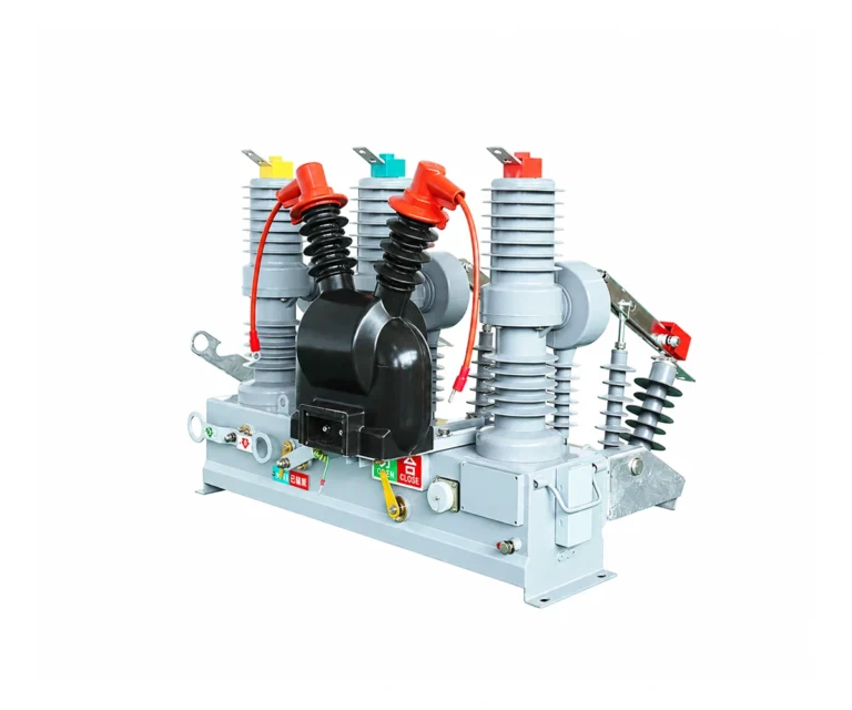
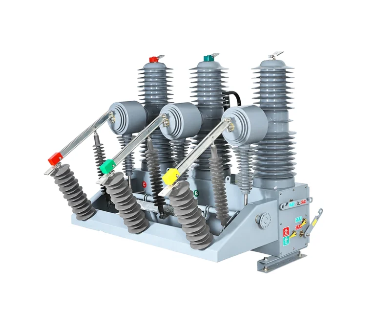
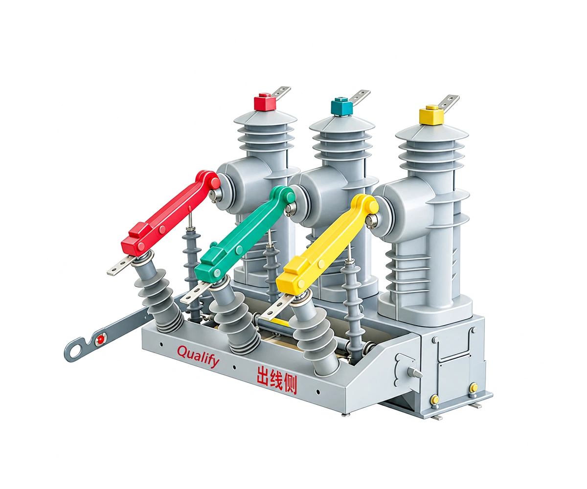
The drawing identifies the disconnector blade, insulating pull rod, support and current transformer. A disconnector is distinct from the vacuum circuit breaker.
01 Stored-Energy Mechanism
The controller drawing is explicitly for a spring operating mechanism and identifies its charging motor circuit.
02 Breaker Control
Closing and trip outputs operate the corresponding coils. Auxiliary contacts provide breaker and stored-energy status.
03 Separate Isolation Function
The external disconnector provides an isolation function separate from interruption in the vacuum circuit breaker. Follow the approved operating procedure.
Interface Coordination
Verify current-input assignment, control supply and plug pinout using the unit-specific drawings. Optional transformer alarm circuits are not a blanket supply-scope claim.
Drawings & Installation Interfaces
Review the supplied drawings for the selected arrangement. Select an image to inspect the full-size original; confirm the approved project revision before installation.
High-Altitude Breaker — General Arrangement
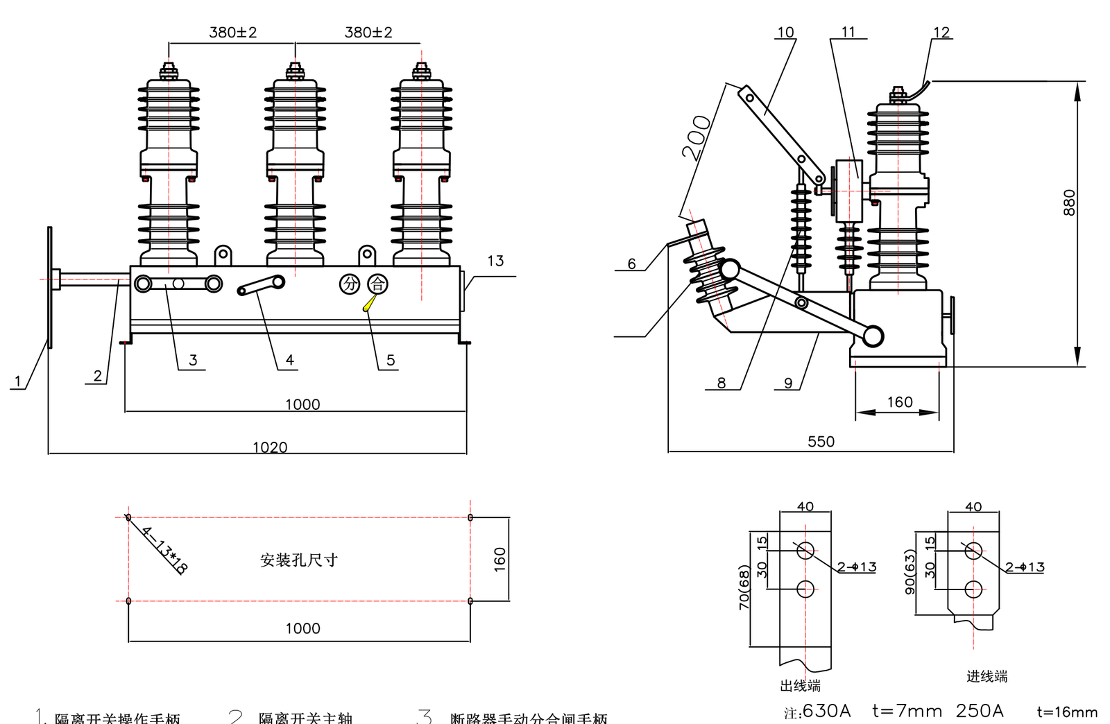
| Front and side views with numbered parts |
| Phase centres: 380 ± 2 mm |
| Mounting centres: 1000 × 160 mm |
| High-altitude designation: ≤ 4000 m |
The sheet combines breaker geometry, disconnector details and terminal interfaces. Its terminal-thickness note is not a complete current-rating table; confirm ratings separately.
FTU Controller — Connection Diagram
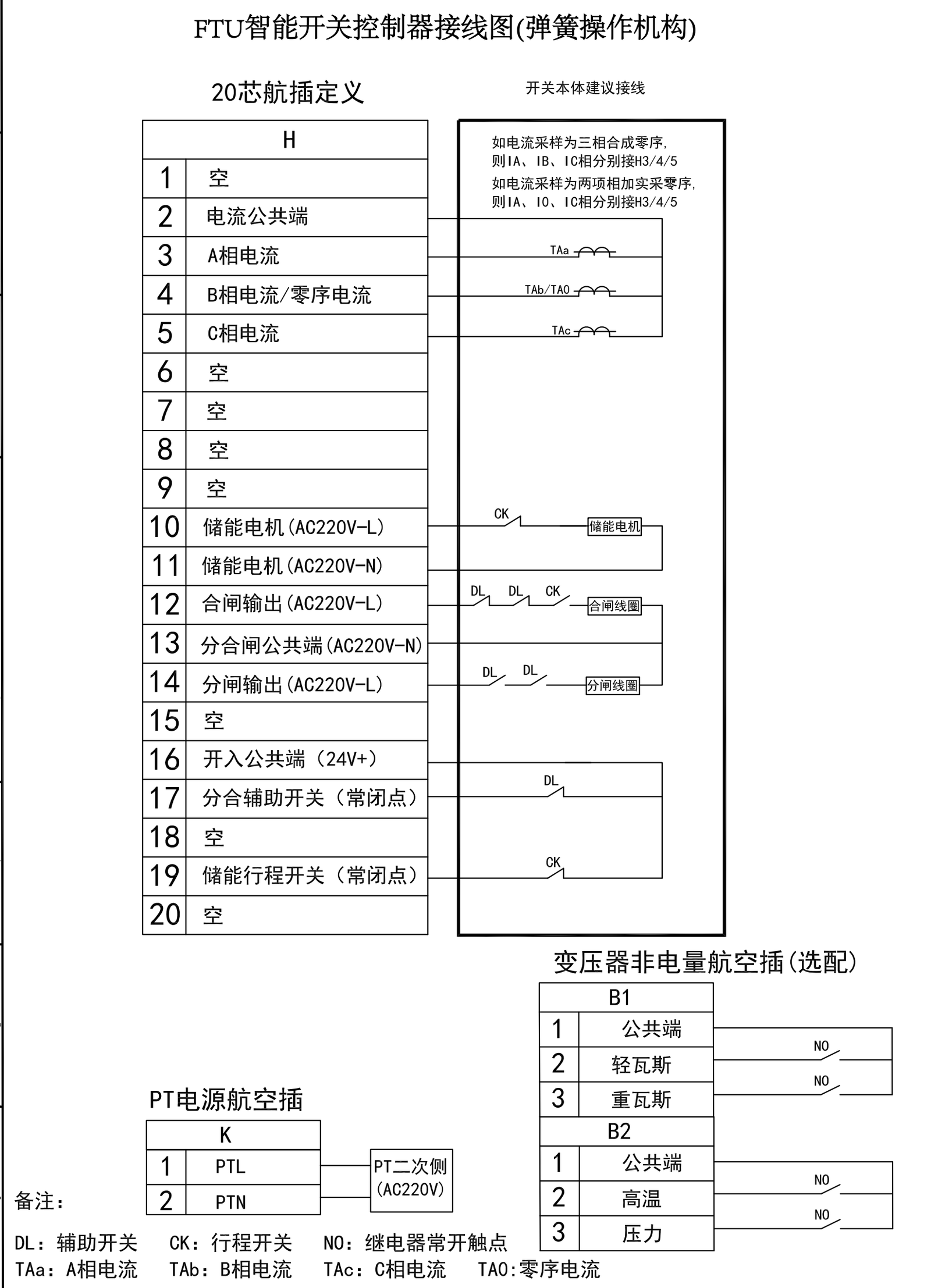
| 20-pin H control connector |
| 2-pin K voltage-transformer supply |
| Spring-mechanism control circuits |
| Optional B1 / B2 transformer alarm inputs |
The original FTU connection sheet identifies current channels, motor supply, closing and trip circuits, and status inputs. Confirm applicability to the selected controller and breaker.
Applications, Features & Procurement Considerations
The supplied two-sheet document covers a ZW32-12 high-altitude arrangement and an FTU controller connection diagram. It is an interface drawing package rather than a complete electrical data sheet.
High-Altitude Arrangement
The drawing is designated for sites at up to 4000 m, subject to confirmation of the complete assembly.
Visible Disconnector
A disconnector blade and operating handle are identified in the general arrangement.
Defined Mounting Pattern
The sheet provides mounting-slot geometry and phase spacing for layout coordination.
FTU Connection Sheet
The second sheet identifies current inputs, control outputs and auxiliary status contacts.
Project-Specific Selection
Obtain the electrical ratings and insulation specification that match this exact arrangement.
Technical Documents & Supply Scope
ZW32-12 · High Altitude Technical Documents
Request the technical package for the selected configuration:
- Approved electrical ratings and model designation.
- General arrangement and mounting drawings.
- Controller wiring and current/voltage sensing details.
- Installation and maintenance instructions.
Inspection & Test Documentation
Request model-specific routine test records and any type-test evidence required by the project. The supplied reference manual alone does not establish certification for the offered equipment.
Agree the applicable standards, editions and evidence with the supplier. Resolve the technical-review items before approving the final data sheet.
Supply Scope to Confirm
- Exact model, ratings and number of units.
- Operating mechanism and auxiliary supply.
- Current/voltage transformers and controller options.
- Disconnectors, supports, cables and accessories.
- Site conditions and approved installation interfaces.
Identify included and excluded equipment explicitly. Confirm that the supplied drawings and controller configuration correspond to the ordered unit.
Maintenance Planning
Prepare the inspection and maintenance plan using the instructions for the delivered assembly and its controller. Confirm operating duty, site exposure and access requirements with the supplier.
Send the network voltage, load current, prospective fault current, control supply, site conditions and required installation arrangement with your inquiry.
Outdoor VCB Breaker FAQ
What does the high-altitude designation mean?
Drawing 1 identifies a ZW32-12 arrangement for an altitude up to 4000 m. Confirm the insulation design and complete assembly rating for the specific site.
What are the current and breaking ratings?
The two supplied sheets do not establish these ratings. Obtain the matching electrical data sheet; values from another ZW32-12 version must not be substituted.
Is a disconnector shown?
Yes. The drawing identifies the disconnector blade, shaft, handle and supporting insulation.
Which controller interface is shown?
The second sheet shows an FTU interface with a 20-pin H connector and a 2-pin K voltage-transformer supply connector.
Are the transformer alarm inputs standard?
The B1 and B2 interfaces are marked as optional in the drawing. Confirm them in the ordered scope.
Can these dimensions be used for fabrication?
They are reference dimensions from the supplied drawing. Obtain an approved drawing matching the ordered unit before fabricating supports or terminals.
Related Products
Explore related vacuum circuit breakers for medium-voltage power distribution and protection applications.