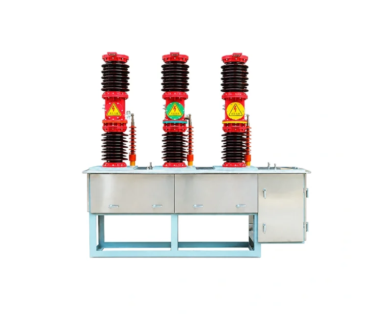
Vacuum Circuit Breakers / VCB Breaker
Baocheng Electrical · Technical review draft
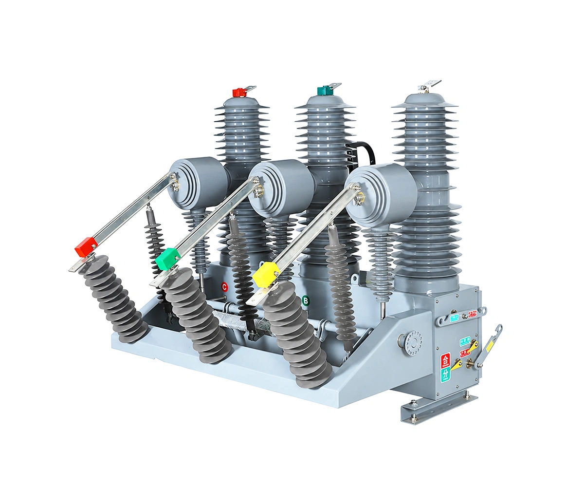
VCB Breaker
ZW32-40.5
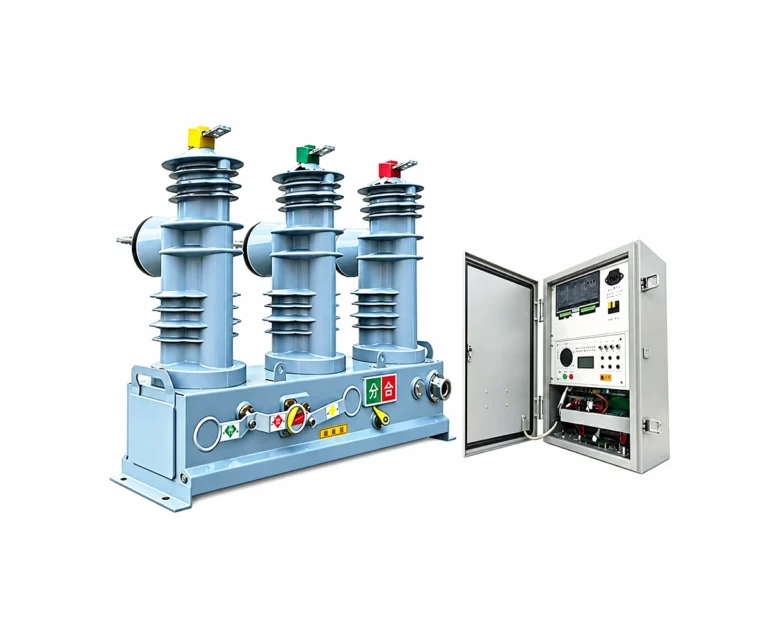
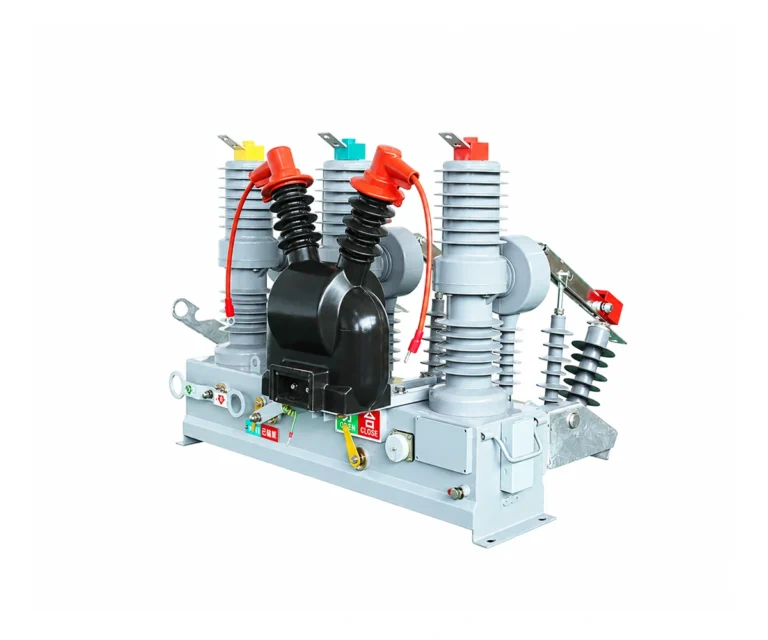
Outdoor vacuum interruption for 35 kV power systems. The supplied ZW32-40.5 manual describes a spring-operated breaker for pole-mounted or substation arrangements, with configurable current transformers and optional recloser control.
40.5 kV · 630 / 1250 / 1600 A · 25 kA | Outdoor vacuum switching
Electrical Characteristics
Nominal system voltage
35 kV
Rated voltage
40.5 kV
Rated normal current
630 / 1250 / 1600 A
Rated short-circuit breaking current
25 kA
About the ZW32-40.5
The document body identifies the equipment as ZW32-40.5, with a 40.5 kV rated voltage for 35 kV network applications. A spring mechanism operates the vacuum interrupters, while optional control equipment supports feeder protection and automatic reclosing.
The source filename says ZW32-33, but the manual body says ZW32-40.5. This page follows the body data and requires confirmation of the commercial model designation.
Technical review draft: confirm the filename/model discrepancy, homepage rating differences and selected installation drawing before publication or ordering.
Technical Specifications — ZW32-40.5
Electrical ratings — manual p. 2
| No. | Parameter | Unit | Value / condition |
|---|---|---|---|
| 1 | Rated voltage | kV | 40.5 |
| 2 | Rated normal current | A | 630 / 1250 / 1600 |
| 3 | Rated frequency, table entry | Hz | 50 / 60; application text describes 50 |
| 4 | Rated short-circuit breaking current | kA | 25 |
| 5 | Rated short-circuit making current | kA peak | 80 |
| 6 | Rated peak withstand current | kA peak | 80 |
| 7 | Rated short-time withstand current | kA | 31.5 |
| 8 | Rated duration of short circuit | s | 4 |
Insulation — manual p. 2
| No. | Parameter | Unit | Value / condition |
|---|---|---|---|
| 1 | Power-frequency withstand, wet / dry | kV | 80 / 95 |
| 2 | Lightning impulse withstand | kV peak | 185 |
| 3 | Secondary circuit withstand | kV | 2 |
Mechanical characteristics — manual p. 2
| No. | Parameter | Unit | Value / condition |
|---|---|---|---|
| 1 | Mechanical endurance | operations | 20000 |
| 2 | Rated short-circuit interruptions | operations | 30 |
| 3 | Closing time | ms | 25–45 |
| 4 | Opening time | ms | 20–45 |
| 5 | Contact gap | mm | 16 ± 1 |
| 6 | Contact overtravel | mm | 4 ± 0.5 |
| 7 | Mass, table entry | kg | 295 |
Control and sensing — manual pp. 1–3
| No. | Parameter | Unit | Value / condition |
|---|---|---|---|
| 1 | Operating mechanism | — | Spring stored-energy |
| 2 | Control voltage, table entry | — | 220 V DC |
| 3 | Current transformers | — | 2 or 3; configuration to confirm |
| 4 | Recloser controller | — | Optional |
| 5 | Voltage-transformer supply | — | Optional; configuration to confirm |
Installation and site confirmation
| No. | Parameter | Unit | Value / condition |
|---|---|---|---|
| 1 | Mounting variants | — | Pole-mounted / substation drawings |
| 2 | Phase spacing | — | Different arrangements shown; use approved drawing |
| 3 | Ambient and altitude limits | — | Not established by supplied operating data |
| 4 | Commercial model designation | — | Filename ZW32-33 / body ZW32-40.5 |
ZW32-40.5: Design & Operating Principle
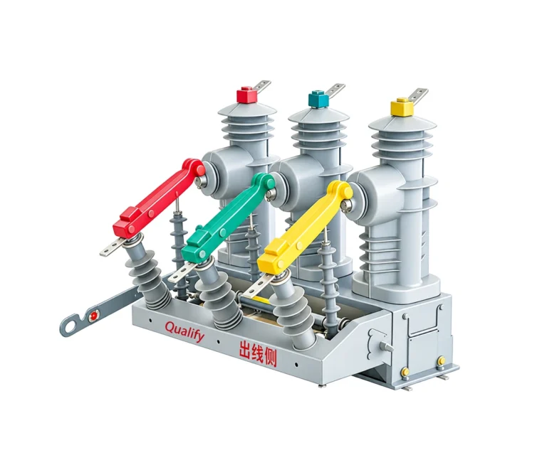
Breaker Assembly — Manual Detail

Isometric detail extracted from manual p. 5. Use the approved arrangement for the ordered unit.
The enclosure supports three insulated poles and the operating mechanism. Current-transformer and controller options depend on the selected configuration.
01 Store Operating Energy
The spring mechanism stores the energy required for breaker operation. Confirm the available control supply and charging arrangement.
02 Operate the Contacts
A close or trip command releases the corresponding mechanism action and drives the interrupter contacts through the linkage.
03 Clear the Fault
The manual lists a 25 kA short-circuit breaking rating. Its separate 31.5 kA short-time withstand value is not the breaking rating.
Optional Protection Package
Current transformers and an optional recloser controller support protection and monitoring. Confirm the controller, CT ratios and auxiliary-power equipment together.
Drawings & Installation Interfaces
Review the supplied drawings for the selected arrangement. Select an image to inspect the full-size original; confirm the approved project revision before installation.
Breaker Body — General Arrangement

| Front, side and plan views |
| Terminal and fixing details shown |
| Original manual geometry retained |
| Select the applicable variant |
The upper drawings on manual p. 5 show the breaker body and its fixing interface. The manual includes differing phase spacings across arrangements; do not combine dimensions from different versions.
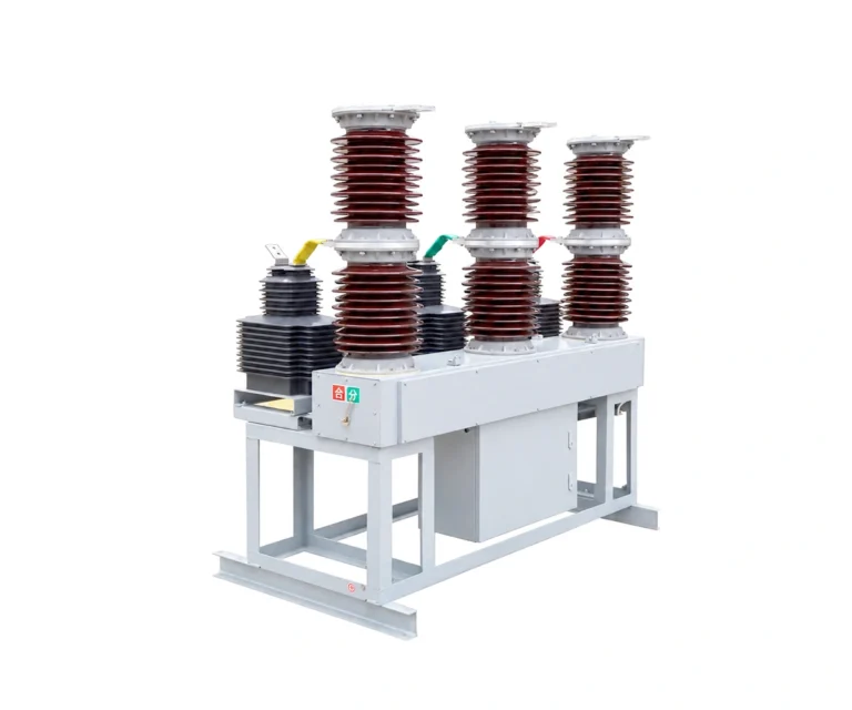
Substation Mounting — Support Arrangement

| Breaker and support structure |
| Front and side installation views |
| Control enclosure shown |
| Approved civil interface required |
The lower drawing on manual p. 5 illustrates a substation mounting arrangement. Confirm support dimensions, foundation details and the selected breaker variant before civil works.
Applications, Features & Procurement Considerations
The document body identifies the equipment as ZW32-40.5, with a 40.5 kV rated voltage for 35 kV network applications. A spring mechanism operates the vacuum interrupters, while optional control equipment supports feeder protection and automatic reclosing.
35 kV System Application
The manual body pairs a 35 kV network application with a 40.5 kV equipment rating.
Spring Mechanism
Stored energy operates the vacuum interrupter contacts.
Optional Recloser Control
The controller option supports an application-specific protection and reclosing scheme.
Current-Transformer Selection
Choose ratios and arrangement for the required measurement and protection duties.
Mounting Alternatives
The manual provides both pole-mounted and substation installation references.
Technical Documents & Supply Scope
ZW32-40.5 Technical Documents
Request the technical package for the selected configuration:
- Approved electrical ratings and model designation.
- General arrangement and mounting drawings.
- Controller wiring and current/voltage sensing details.
- Installation and maintenance instructions.
Inspection & Test Documentation
Request model-specific routine test records and any type-test evidence required by the project. The supplied reference manual alone does not establish certification for the offered equipment.
Agree the applicable standards, editions and evidence with the supplier. Resolve the technical-review items before approving the final data sheet.
Supply Scope to Confirm
- Exact model, ratings and number of units.
- Operating mechanism and auxiliary supply.
- Current/voltage transformers and controller options.
- Disconnectors, supports, cables and accessories.
- Site conditions and approved installation interfaces.
Identify included and excluded equipment explicitly. Confirm that the supplied drawings and controller configuration correspond to the ordered unit.
Maintenance Planning
Prepare the inspection and maintenance plan using the instructions for the delivered assembly and its controller. Confirm operating duty, site exposure and access requirements with the supplier.
Send the network voltage, load current, prospective fault current, control supply, site conditions and required installation arrangement with your inquiry.
VCB Breaker FAQ
Why does the page say ZW32-40.5?
The filename says ZW32-33, but the manual body and model explanation identify ZW32-40.5. Confirm the final commercial designation before publication.
What is the nominal system voltage?
The manual describes 35 kV network applications with a 40.5 kV equipment rated voltage.
Is the breaking rating 25 kA or 31.5 kA?
The manual lists 25 kA for short-circuit breaking and 31.5 kA for short-time withstand. These are different duties and must not be interchanged.
Can it be installed in a substation?
The manual contains a substation support arrangement as well as a pole-mounted installation reference. The selected structure requires approved project drawings.
Is the recloser controller standard?
It is described as an option. Confirm the controller, CT arrangement, VT supply and communication requirements in the order.
Can the listed dimensions be combined?
No. The manual shows different arrangements and phase spacings. Use one approved drawing set corresponding to the ordered variant.
Related Products
Explore related vacuum circuit breakers for medium-voltage power distribution and protection applications.